
Integrated Pump Skid Selection Guide
Compare 4 models from 600 to 2000 kW and match the equipment to your cooling loop.
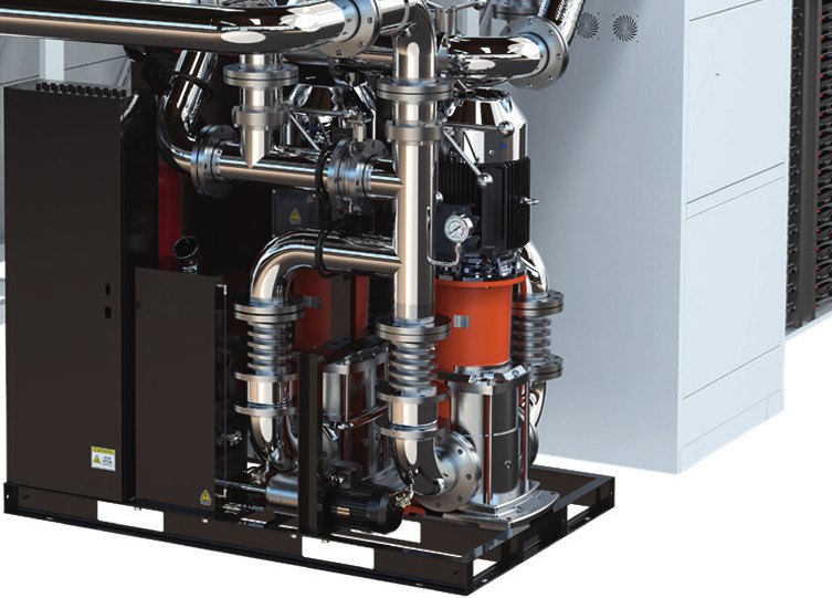
Primary-loop circulation
How it is used
Locate the integrated pump skid between the heat-rejection plant and the CDU primary circuit for circulation, filtration and refill.
Selection checkpoint
Check the complete system curve, static pressure, expansion and freeze protection.
Illustrative architecture, not a customer installation or an installation drawing.
Where this equipment fits
For primary-side circulation for 600 kW liquid-cooled halls (dry cooler / tower ↔ CDUs). When the dry cooler or tower has no pumps, or the pump room is separate, the skid handles primary circulation, filtration and refill; piping, electrical and controls are integrated at the factory, leaving only flanges and power on site. Combines with TC-DCU dry coolers and in-row CDUs for a turnkey primary side.
Compare the model range
| Model | Capacity | Rated flow | Size / height | English datasheet |
|---|---|---|---|---|
| TC-IPS-600 | 600 kW | 2000 L/min | 2000 × 1400 × 2000 mm | ↓ Download PDF |
| TC-IPS-1000 | 1000 kW | 3200 L/min | 2200 × 1400 × 2000 mm | ↓ Download PDF |
| TC-IPS-1600 | 1600 kW | 4000 L/min | 2200 × 1500 × 2000 mm | ↓ Download PDF |
| TC-IPS-2000 | 2000 kW | 5000 L/min | 2200 × 1500 × 2000 mm | ↓ Download PDF |
Selection workflow
- Establish the design heat load and the required redundancy or future capacity margin.
- Confirm the source and sink temperatures. Liquid-to-air capacity depends on room inlet air; liquid-to-liquid capacity depends on facility water and approach temperature.
- Calculate required coolant flow using the actual fluid properties and temperature rise.
- Check the pump curve against the complete loop pressure drop, including cold plates, manifolds, hoses, filters and connections.
- Confirm mounting space, maintenance access, electrical supply, connections, controls and site conditions.
- Agree the acceptance test, drawings, communication register map and commissioning scope before ordering.
Flow and thermal sizing
Q = 60,000 × P / (ρ × cp × ΔT), where Q is L/min, P is kW, ρ is kg/m³, cp is kJ/(kg·K), and ΔT is K. Use fluid properties at the design temperature. Thermal flow alone does not establish available pump head or guaranteed system capacity.
Note: matching capacity converted at PG40 and a 5 °C gap; final selection per loop flow and pressure-drop calculation. Specifications subject to change.
Installation and service checks
- Maintain access for pump, filter and heat-exchanger service.
- Confirm all wetted materials and seals are compatible with the specified coolant.
- Agree flushing, filling, venting, leak testing and alarm verification procedures.
- Validate BMS / DCIM communication and automatic switchover under the agreed test conditions.
Documentation to request
Supplied: dimensional / connection drawing, P&ID, Modbus register map, flow–pressure-drop curve, selection table, user manual. Factory tests: pressure hold, leak test, flow resistance at rated flow, pump / ATS switchover, leak-sensor / coolant-quality / comms check; records ship with every unit. Combined dry cooler + pump skid + CDU commissioning record for primary-side projects.
Get a CDU selection review
Send your rack or loop heat load, inlet temperature, coolant, required flow, pressure drop, power supply and available space. We will confirm the model and operating conditions.
Sample lead time: 6–8 weeks. Large primary-side production units: 8–10 weeks, subject to project confirmation.

