
Coolant Distribution Units & Primary-Side Cooling
Six product families. 29 models. From 6 kW rack cooling to 2 MW facility loops.
Compare liquid-to-air and liquid-to-liquid CDUs, integrated dry cooling units and pump skids with model-specific specifications and English datasheets.
Explore all models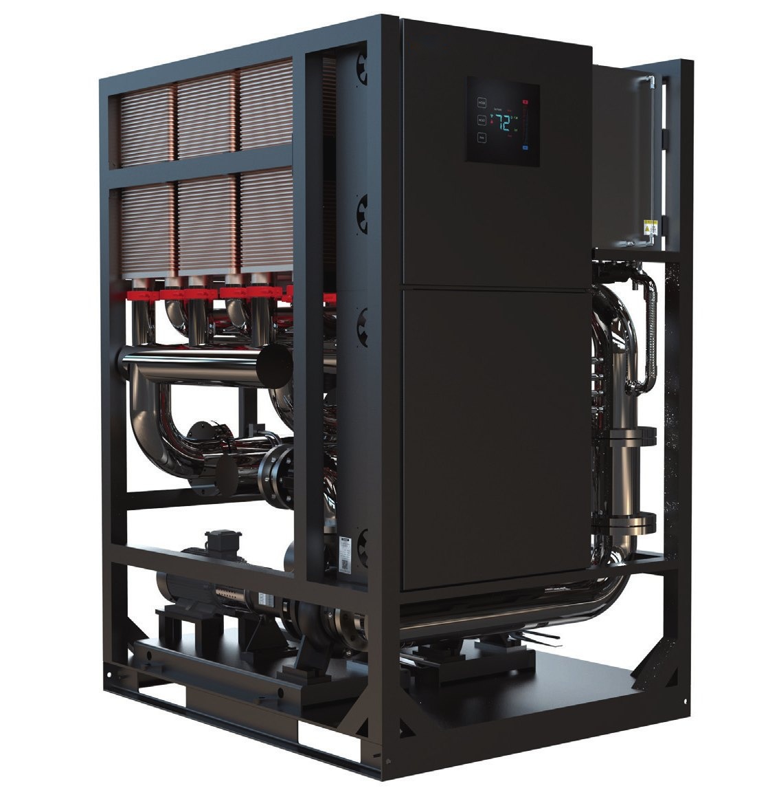
Find the right cooling architecture
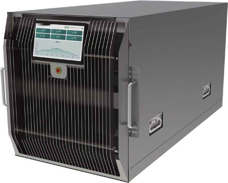
In-Rack Liquid-to-Air CDU
4 models · product specifications and English PDFs
Compare models →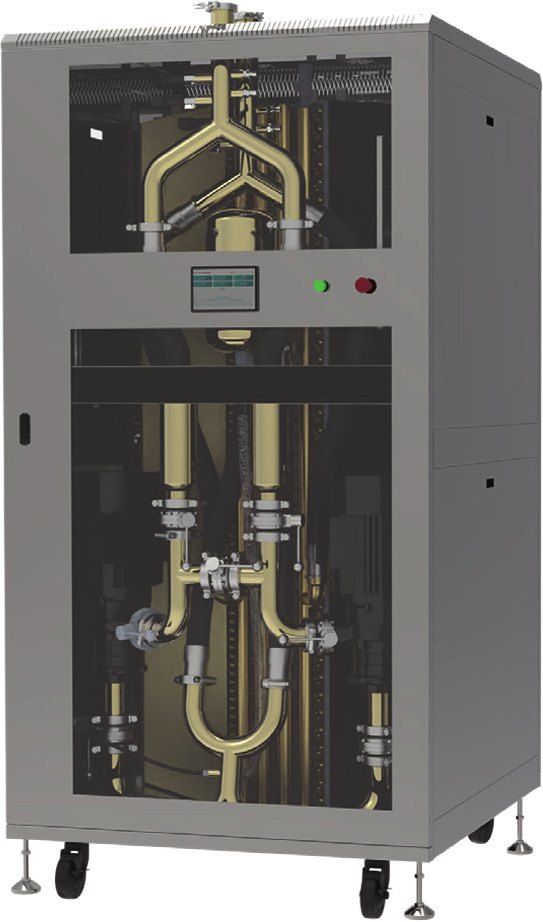
In-Row Liquid-to-Air CDU
4 models · product specifications and English PDFs
Compare models →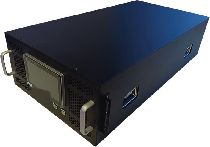
In-Rack Liquid-to-Liquid CDU
7 models · product specifications and English PDFs
Compare models →In-Row Liquid-to-Liquid CDU
5 models · product specifications and English PDFs
Compare models →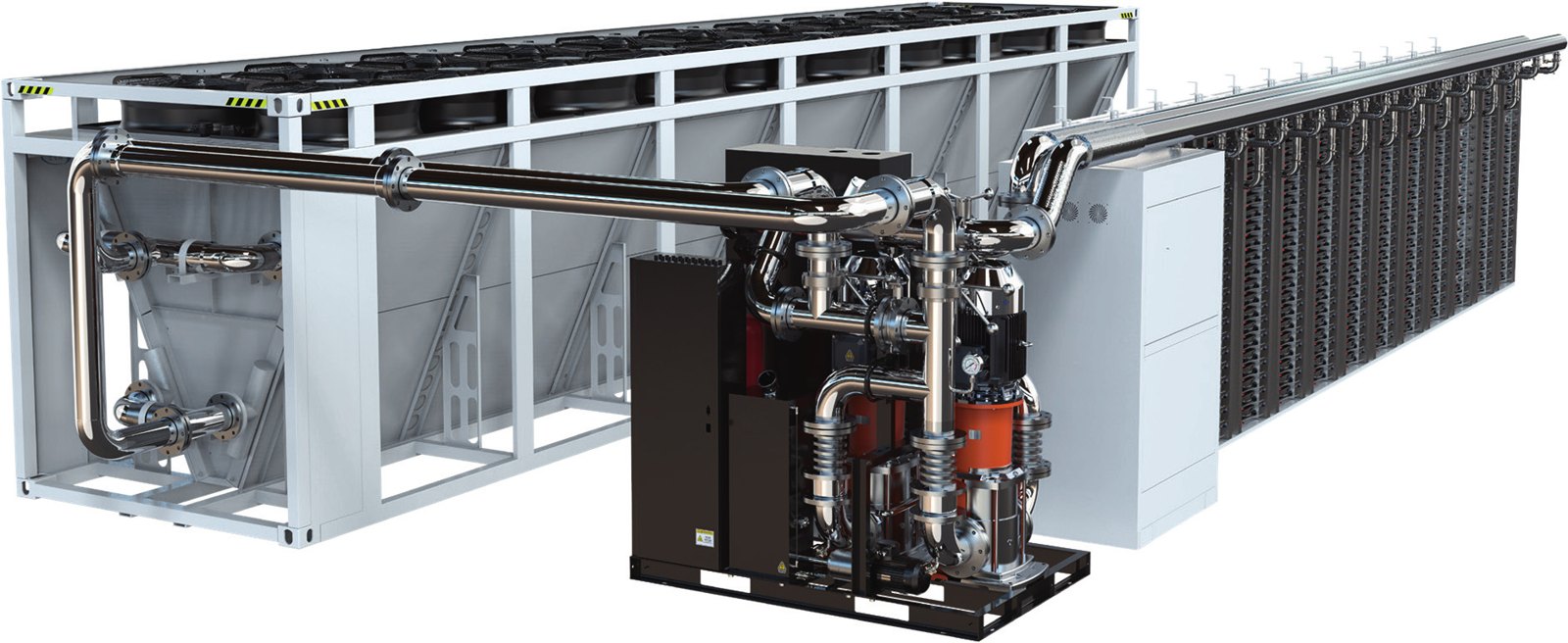
Integrated Dry Cooling Unit
5 models · product specifications and English PDFs
Compare models →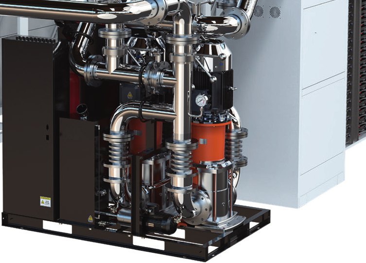
Integrated Pump Skid
4 models · product specifications and English PDFs
Compare models →Application architectures
Match the CDU to the heat source, available heat sink and hydraulic requirements.
Edge rooms & pilot racks
How it is used
Add direct-to-chip cooling where facility water is unavailable. The room cooling system must remove the heat rejected by the CDU.
Selection checkpoint
Confirm inlet air temperature, rack space and room heat-rejection capacity.
Illustrative architecture, not a customer installation or an installation drawing.
AI clusters in existing air-cooled rooms
How it is used
Place the liquid-to-air cabinet alongside GPU racks to serve a local cooling loop without a facility-water connection.
Selection checkpoint
Check return-air paths, cabinet service clearance and total room cooling load.
Illustrative architecture, not a customer installation or an installation drawing.
High-density GPU racks
How it is used
Separate the facility-water loop from the rack coolant loop through a rack-mounted liquid-to-liquid CDU.
Selection checkpoint
Confirm facility-water temperature, available pressure and secondary-loop pressure drop.
Illustrative architecture, not a customer installation or an installation drawing.
Multi-rack AI halls & modular PODs
How it is used
Use an in-row CDU to distribute cooling to several racks. Size the loop against the actual IT load and redundancy requirement.
Selection checkpoint
Validate the manifold layout, pump curve and operating load for each project.
Illustrative architecture, not a customer installation or an installation drawing.
Outdoor heat rejection
How it is used
Connect the dry cooling unit to the facility side of the CDU. Available cooling capacity depends on outdoor air and required liquid temperature.
Selection checkpoint
Check summer ambient, winter freeze protection, sound limits and maintenance access.
Illustrative architecture, not a customer installation or an installation drawing.
Primary-loop circulation
How it is used
Locate the integrated pump skid between the heat-rejection plant and the CDU primary circuit for circulation, filtration and refill.
Selection checkpoint
Check the complete system curve, static pressure, expansion and freeze protection.
Illustrative architecture, not a customer installation or an installation drawing.
Select the cooling architecture
| Architecture | Heat sink | Typical fit |
|---|---|---|
| Liquid-to-air CDU | Room air | Retrofits and installations without facility water; room cooling must absorb the rejected heat. |
| Liquid-to-liquid CDU | Facility water loop | Higher-density racks and multi-rack installations with available facility water. |
| Dry cooling unit | Outdoor air | Primary-side heat rejection; assess climate and required coolant temperature. |
| Pump skid | Hydraulic circulation | Primary-loop pumping, filtration and refill; pair with a suitable heat-rejection source. |
In-Rack Liquid-to-Air CDU
| Model | Capacity | Rated flow | Size / height | English datasheet |
|---|---|---|---|---|
| TC-CDU-A6R | 6 kW | 10 L/min | 6U | ↓ Download PDF |
| TC-CDU-A15R | 15 kW | 25 L/min | 10U | ↓ Download PDF |
| TC-CDU-A24R | 24 kW | 40 L/min | 15U | ↓ Download PDF |
| TC-CDU-A30R | 30 kW | 50 L/min | 20U | ↓ Download PDF |
In-Row Liquid-to-Air CDU
| Model | Capacity | Rated flow | Size / height | English datasheet |
|---|---|---|---|---|
| TC-CDU-A60C | 60 kW | 100 L/min | 600 × 1200 × 2000 mm | ↓ Download PDF |
| TC-CDU-A120C | 120 kW | 200 L/min | 1200 × 1200 × 2000 mm | ↓ Download PDF |
| TC-CDU-A300C | 300 kW | 500 L/min | 3000 × 1200 × 2000 mm | ↓ Download PDF |
| TC-CDU-A600C | 600 kW | 1000 L/min | 6000 × 1200 × 2000 mm | ↓ Download PDF |
In-Rack Liquid-to-Liquid CDU
| Model | Capacity | Rated flow | Size / height | English datasheet |
|---|---|---|---|---|
| TC-CDU-L35R | 35 kW | 120 L/min | 4U | ↓ Download PDF |
| TC-CDU-L50R | 50 kW | 160 L/min | 4U | ↓ Download PDF |
| TC-CDU-L100R | 100 kW | 160 L/min | 4U | ↓ Download PDF |
| TC-CDU-L120R | 120 kW | 190 L/min | 5U | ↓ Download PDF |
| TC-CDU-L150R | 150 kW | 240 L/min | 5U | ↓ Download PDF |
| TC-CDU-L200R | 200 kW | 320 L/min | 6U | ↓ Download PDF |
| TC-CDU-L250R | 250 kW | 400 L/min | 6U | ↓ Download PDF |
In-Row Liquid-to-Liquid CDU
| Model | Capacity | Rated flow | Size / height | English datasheet |
|---|---|---|---|---|
| TC-CDU-L300C | 300 kW | 500 L/min | 600 × 1200 × 2000 mm | ↓ Download PDF |
| TC-CDU-L600C | 600 kW | 1000 L/min | 600 × 1200 × 2200 mm | ↓ Download PDF |
| TC-CDU-L1000C | 1000 kW | 1800 L/min | 1200 × 1500 × 2000 mm | ↓ Download PDF |
| TC-CDU-L1600C | 1600 kW | 2500 L/min | 1200 × 1500 × 2000 mm | ↓ Download PDF |
| TC-CDU-L2000C | 2000 kW | 3200 L/min | 1200 × 1500 × 2200 mm | ↓ Download PDF |
Integrated Dry Cooling Unit
| Model | Capacity | Rated flow | Size / height | English datasheet |
|---|---|---|---|---|
| TC-DCU-300 | 300 kW | 1000 L/min | 3300 × 2280 × 2535 mm | ↓ Download PDF |
| TC-DCU-600 | 600 kW | 2000 L/min | 6600 × 2280 × 2535 mm | ↓ Download PDF |
| TC-DCU-1000 | 1000 kW | 3200 L/min | 6600 × 2280 × 2535 mm | ↓ Download PDF |
| TC-DCU-1600 | 1600 kW | 4000 L/min | 13300 × 2280 × 2535 mm | ↓ Download PDF |
| TC-DCU-2000 | 2000 kW | 5000 L/min | 13300 × 2280 × 2535 mm | ↓ Download PDF |
| TC-DC1000 V-type dry cooler | 1000 kW class (40 °C ambient) | 162 m³/h (EG30, 55 → 49 °C) | 4700 mm long × 2550 mm high | ↓ Download PDF |
Integrated Pump Skid
| Model | Capacity | Rated flow | Size / height | English datasheet |
|---|---|---|---|---|
| TC-IPS-600 | 600 kW | 2000 L/min | 2000 × 1400 × 2000 mm | ↓ Download PDF |
| TC-IPS-1000 | 1000 kW | 3200 L/min | 2200 × 1400 × 2000 mm | ↓ Download PDF |
| TC-IPS-1600 | 1600 kW | 4000 L/min | 2200 × 1500 × 2000 mm | ↓ Download PDF |
| TC-IPS-2000 | 2000 kW | 5000 L/min | 2200 × 1500 × 2000 mm | ↓ Download PDF |
Cold plate, manifold and CDU integration
Specify the cooling loop as a system: fluid compatibility, flow distribution, connection pressure drop, temperature limits and controls all affect the result.
Explore liquid cooling manifoldsGet a CDU selection review
Send your rack or loop heat load, inlet temperature, coolant, required flow, pressure drop, power supply and available space. We will confirm the model and operating conditions.
Request an engineering reviewSample lead time: 8–10 weeks. Production lead time depends on the model and is confirmed in the quotation.

