
TC-CDU-A60C In-Row Liquid-to-Air CDU (60 kW)
Liquid-to-Air Coolant Distribution Unit · 60 kW · In-row · liquid cooling without facility water
English PDF · Free download · No form required
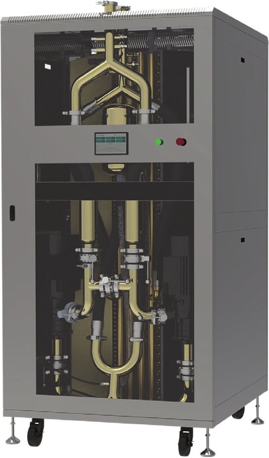
AI clusters in existing air-cooled rooms
How it is used
Place the liquid-to-air cabinet alongside GPU racks to serve a local cooling loop without a facility-water connection.
Selection checkpoint
Check return-air paths, cabinet service clearance and total room cooling load.
Illustrative architecture, not a customer installation or an installation drawing.
Overview
- Liquid-to-air CDU: PG25 to the cold plates on the secondary side, heat rejected to room air by the built-in heat exchanger and fans, no facility water required
- 60 kW rated at 25 °C inlet air, 10 °C approach, 100 LPM secondary flow, variable 20–100%
- 1+1 redundant pumps with auto switchover, dual-feed ATS, leak detection, coolant quality monitoring, 25 µm filter, bypass online-replaceable filter and auto refill
- PID control of both airflow and coolant flow; Modbus RTU / TCP for BMS / DCIM
- In-row floor-standing, 600 × 1200 × 2000 mm, approx. 350 kg, IP55
- For retrofit rooms and small AI clusters without chilled water or cooling towers
Engineering fit
For retrofit rooms and small AI clusters without chilled water or cooling towers: only power and room air conditioning are needed to run direct-to-chip liquid cooling — no chilled water or cooling tower. 35 °C secondary supply is obtained from 25 °C room inlet air (10 °C approach); capacity derates with warmer room air per the selection table. Pairs with ToneCooling cold plates, manifolds and hose assemblies from the same factory.
- Retrofits without chilled water or cooling towers, a row of racks with 60 kW on liquid
- Phased builds of small AI clusters using room air conditioning for heat rejection
- Direct-to-chip cooling in edge / regional data centres
- Indoor alternative to an outdoor dry-cooler loop
Key specifications
| Parameter | Specification |
|---|---|
| Rated cooling capacity | 60 kW |
| Installation | In-row, floor-standing |
| Dimensions (W × D × H) | 600 × 1200 × 2000 mm |
| Weight | approx. 350 kg |
| Coolant | PG25 (25 % propylene glycol / water) |
| Power supply | AC 220 V, 50/60 Hz |
| Dual-feed ATS | Yes |
| Power consumption | < 3.5 kW |
| Ingress protection | IP55 |
| Display | 10.1″ touch HMI |
Performance & control
| Parameter | Specification |
|---|---|
| Approach temperature | 10 °C |
| Primary air in / out | 25 °C / 35 °C |
| Secondary liquid out / in | 35 °C / 45 °C |
| Secondary rated flow | 100 LPM |
| Flow range | 20–100% |
| Pump head | 25 m |
| Redundant pumps, auto switchover | 1+1 |
| Control | PID, airflow and flow vs. temperature |
| Flow check | 60,000 × 60 ÷ (1030 × 3.9 × 10 K) ≈ 90 LPM; 100 LPM rated incl. margin (ρ in kg/m³, cp in kJ/kg·K; ΔT in K) |
Monitoring · interfaces · environment
| Parameter | Specification |
|---|---|
| Leak detection | Yes |
| Coolant quality monitoring | Yes |
| Secondary filter | 25 µm |
| Bypass online-replaceable filter | Yes |
| Automatic refill | Yes |
| Communication | Modbus RTU & TCP/IP |
| Operating environment | −10 to 55 °C, 5–90 % RH |
| Storage environment | −45 to 70 °C, 5–93 % RH |
| Heat rejection | Built-in fans to room air; 25 °C inlet air and a return-air path required |
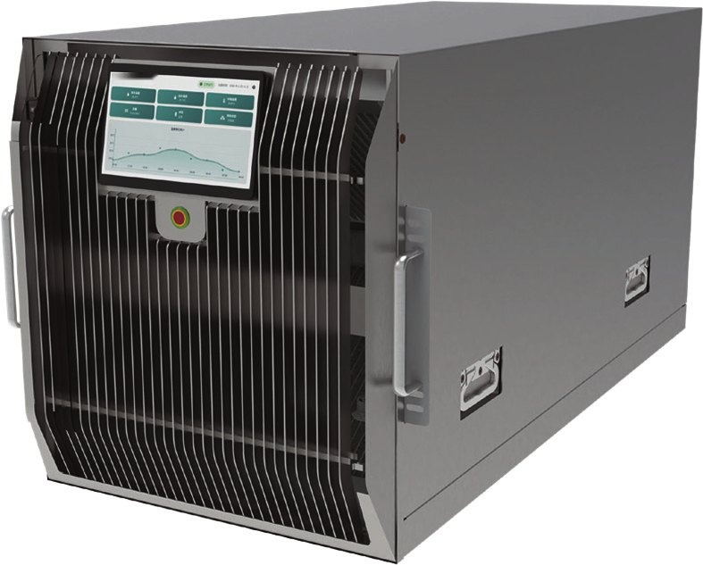
Note: rated at 25 °C inlet air, 35 °C secondary supply, PG25; derate per selection table for other inlet air temperatures. Platform names indicate compatibility only and imply no endorsement or partnership. Specifications subject to change.
Documents and factory tests
Supplied: dimensional / connection drawing, P&ID, Modbus register map, flow–pressure-drop curve, selection table, user manual. Factory tests: pressure hold, leak test, flow resistance at rated flow, pump / ATS switchover, leak-sensor / coolant-quality / comms check; records ship with every unit. Combined cold plate + manifold + CDU report for full-rack projects.
Compare models in this series
| Model | Capacity | Rated flow | Size / height | English datasheet |
|---|---|---|---|---|
| TC-CDU-A60C | 60 kW | 100 L/min | 600 × 1200 × 2000 mm | ↓ Download PDF |
| TC-CDU-A120C | 120 kW | 200 L/min | 1200 × 1200 × 2000 mm | ↓ Download PDF |
| TC-CDU-A300C | 300 kW | 500 L/min | 3000 × 1200 × 2000 mm | ↓ Download PDF |
| TC-CDU-A600C | 600 kW | 1000 L/min | 6000 × 1200 × 2000 mm | ↓ Download PDF |
Frequently asked questions
Under what conditions is the 60 kW rating valid?
Rated at 25 °C inlet air, 35 °C secondary supply and PG25. Usable capacity derates as room return air gets warmer; size the unit for the actual inlet air temperature.
Liquid-to-air or liquid-to-liquid CDU?
Choose liquid-to-air when the room has no chilled water or cooling tower, or when the water system must not be touched — room air conditioning removes the heat. Choose liquid-to-liquid when facility water exists and the load is large; it uses less energy per kW. Secondary connections are the same, so you can migrate later.
How much room cooling is needed?
The unit rejects the 60 kW cold-plate load into room air, so room CRAC/CRAH capacity must grow by 60 kW sensible, with hot/cold aisle airflow kept separate.
Which coolant on the secondary side?
Closed PG25 (25 % propylene glycol / water) loop with 25 µm filtration, cleaned at the factory and pre-filled on request.
Which protocols are supported?
Modbus RTU and Modbus TCP/IP are standard; the register map ships with the unit. Ask about other protocols when requesting a quote.
Lead time?
Standard units ship in 6–8 weeks; every unit ships with pressure, leak and flow-resistance test records.
Get a CDU selection review
Send your rack or loop heat load, inlet temperature, coolant, required flow, pressure drop, power supply and available space. We will confirm the model and operating conditions.
Sample lead time: 6–8 weeks. Large primary-side production units: 8–10 weeks, subject to project confirmation.

