
In-Row Liquid-to-Air CDU Selection Guide
Compare 4 models from 60 to 600 kW and match the equipment to your cooling loop.
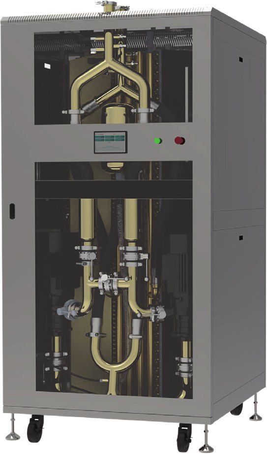
AI clusters in existing air-cooled rooms
How it is used
Place the liquid-to-air cabinet alongside GPU racks to serve a local cooling loop without a facility-water connection.
Selection checkpoint
Check return-air paths, cabinet service clearance and total room cooling load.
Illustrative architecture, not a customer installation or an installation drawing.
Where this equipment fits
For retrofit rooms and small AI clusters without chilled water or cooling towers: only power and room air conditioning are needed to run direct-to-chip liquid cooling — no chilled water or cooling tower. 35 °C secondary supply is obtained from 25 °C room inlet air (10 °C approach); capacity derates with warmer room air per the selection table. Pairs with ToneCooling cold plates, manifolds and hose assemblies from the same factory.
Compare the model range
| Model | Capacity | Rated flow | Size / height | English datasheet |
|---|---|---|---|---|
| TC-CDU-A60C | 60 kW | 100 L/min | 600 × 1200 × 2000 mm | ↓ Download PDF |
| TC-CDU-A120C | 120 kW | 200 L/min | 1200 × 1200 × 2000 mm | ↓ Download PDF |
| TC-CDU-A300C | 300 kW | 500 L/min | 3000 × 1200 × 2000 mm | ↓ Download PDF |
| TC-CDU-A600C | 600 kW | 1000 L/min | 6000 × 1200 × 2000 mm | ↓ Download PDF |
Selection workflow
- Establish the design heat load and the required redundancy or future capacity margin.
- Confirm the source and sink temperatures. Liquid-to-air capacity depends on room inlet air; liquid-to-liquid capacity depends on facility water and approach temperature.
- Calculate required coolant flow using the actual fluid properties and temperature rise.
- Check the pump curve against the complete loop pressure drop, including cold plates, manifolds, hoses, filters and connections.
- Confirm mounting space, maintenance access, electrical supply, connections, controls and site conditions.
- Agree the acceptance test, drawings, communication register map and commissioning scope before ordering.
Flow and thermal sizing
Q = 60,000 × P / (ρ × cp × ΔT), where Q is L/min, P is kW, ρ is kg/m³, cp is kJ/(kg·K), and ΔT is K. Use fluid properties at the design temperature. Thermal flow alone does not establish available pump head or guaranteed system capacity.
Note: rated at 25 °C inlet air, 35 °C secondary supply, PG25; derate per selection table for other inlet air temperatures. Platform names indicate compatibility only and imply no endorsement or partnership. Specifications subject to change.
Installation and service checks
- Maintain access for pump, filter and heat-exchanger service.
- Confirm all wetted materials and seals are compatible with the specified coolant.
- Agree flushing, filling, venting, leak testing and alarm verification procedures.
- Validate BMS / DCIM communication and automatic switchover under the agreed test conditions.
Documentation to request
Supplied: dimensional / connection drawing, P&ID, Modbus register map, flow–pressure-drop curve, selection table, user manual. Factory tests: pressure hold, leak test, flow resistance at rated flow, pump / ATS switchover, leak-sensor / coolant-quality / comms check; records ship with every unit. Combined cold plate + manifold + CDU report for full-rack projects.
Get a CDU selection review
Send your rack or loop heat load, inlet temperature, coolant, required flow, pressure drop, power supply and available space. We will confirm the model and operating conditions.
Sample lead time: 8–10 weeks. Production lead time depends on the model and is confirmed in the quotation.

