This comprehensive guide covers 3d battery cooling plate solutions for industrial and OEM applications. ToneCooling provides expert insights on 3d battery cooling plate technology and implementation.
Research Background
Electric vehicles are a primary solution for decarbonizing transportation, and lithium-ion batteries—renowned for their longevity, high energy and power density, and minimal self-discharge—play a pivotal role in this transition. However, the operational efficiency, safety, and lifespan of lithium-ion batteries are significantly influenced by their thermal environment. Previous studies have demonstrated that lithium-ion batteries operate most efficiently at temperatures between 15 and 35°C, with a temperature differential between batteries kept below 5°C. Therefore, it is essential to develop and optimize an effective battery thermal management system (BTMS).
Research Content
In this study, the lithium-ion battery pack comprises 20 series-connected cylindrical cells, each measuring 65 mm × 18 mm × 140 mm. To enhance heat transfer from the battery to the liquid cooling plate (LCP), a 1 mm thick aluminum plate is inserted between every two adjacent cells. For the LCP-based battery thermal management system (BTMS), three typical straight-channel LCP cooling structures were initially designed, as illustrated in Figures 1(a)–(c).

First, the performance of the Battery Thermal Management System (BTMS) designed with Battery Cooling Plates (BCP) and Side-Directed Cooling Plates (SDCP) was investigated and compared. In the SDCP configuration, the positioning of the cooling plate inlets was also taken into account. Specifically, when the inlets of the two cooling plates were on the same side, resulting in identical coolant flow directions, it was designated as SDCP-A. Conversely, when the inlets were positioned on opposite sides, leading to opposing coolant flow directions, it was referred to as SDCP-B.

Figure 3 illustrates the Tmax and ΔTmax of the BCP and BDCP designs throughout the exhaust process. It is noteworthy that, although there is no significant difference in the Tmax and ΔTmax curves between the BDCP and BCP designs, the Tmax and ΔTmax values for the BCP design consistently remain lower than those for the BDCP design. This suggests that, during the exhaust process, the impact of reducing the coolant flow rate on cooling performance is more pronounced than the effect of increasing the heat exchange area, leading to the comparatively weaker cooling performance of the BDCP design. At t = 1080 s, the Tmax and ΔTmax for the BDCP design increased by 0.52 K and 0.27 K, respectively, in comparison to the BCP design. However, it is important to note that the difference in cooling performance between the BDCP and BCP designs is relatively minor when compared to the SDCP design.

Figure 4 illustrates the impact of the coolant inlet position on the temperature distribution characteristics of the 3DCP design. For the 3DCP design, positioning the coolant inlet on the bottom surface and the coolant outlet on the side surface yields superior battery cooling performance compared to having the coolant inlet on the side surface. Specifically, when the coolant mass flow rate (mco) is set at 20.0 g•s⁻¹, the maximum temperature (Tmax) and the maximum temperature difference (ΔTmax) for the 3DCP-A and 3DCP-B designs with a bottom coolant inlet are reduced by 1.6 K and 2.8 K, respectively, in comparison to the side coolant inlet configuration. Furthermore, the 3DCP-B design incorporates an additional cooling section in the middle of the battery pack, which effectively manages heat in that region. Consequently, the overall temperature uniformity is enhanced, particularly when combined with the bottom coolant inlet configuration. This improvement significantly lowers both Tmax and ΔTmax. Notably, when mco is 5.0 g•s⁻¹ and the coolant inlet is positioned on the bottom surface, the Tmax and ΔTmax for the 3DCP-B design are recorded at only 303.3 K and 4.3 K, respectively, which are 0.87 K and 0.89 K lower than those of the 3DCP-A design. Therefore, for the 3DCP design, subsequent analyses will be based on the configuration with the coolant inlet located on the bottom surface. Reason: Improved clarity, vocabulary, and technical accuracy while maintaining the original meaning.

In addition, Figure 5 illustrates the cooling effect of the 3DCP-B design under varying ambient temperatures (Ta). This portion of the study was conducted with an inlet temperature (Tin) of 298.0 K. Ta is positively correlated with both the maximum temperature (Tmax) and the temperature difference (ΔTmax). As Ta increases from 293.0 K to 303.0 K, Tmax and ΔTmax rise by 2.2 K and 1.7 K, respectively. Notably, when Ta is equal to or greater than 298.0 K, ΔTmax exceeds 5.0 K. This section examines the change in Ta from 293.0 K to 303.0 K in 2.5 K intervals, revealing that the difference in Tmax among the five cases is 2.5 K during the initial discharge process. However, near the end of the discharge, the average difference in Tmax between adjacent operating conditions decreases to only 0.55 K. This finding indicates that the influence of Ta on Tmax is most pronounced during the initial discharge phase, gradually diminishing toward the end. Although the aforementioned studies demonstrate that the thermal management performance of the three-dimensional cooling plate surpasses that of the traditional straight-channel cooling plate, its increased complexity inevitably leads to higher manufacturing costs and a greater risk of coolant leakage. Therefore, future research should further investigate the effectiveness of 3DCP-B-based battery thermal management systems (BTMS), including optimizing the flow channel configuration and proposing innovative designs.

Conclusion and Outlook
In summary, the placement strategy of the conventional direct-flow cooling plate significantly impacts the temperature distribution within the battery pack. Compared to the BCP design, multiple cooling plates result in a lower coolant flow rate at each plate, leading to decreased thermal management efficiency of the battery pack. However, the use of multiple cooling plates can mitigate the thermal performance disparities between battery cells. Under the studied operating conditions, the maximum temperature difference between the cells at both ends of the battery pack using BDCP is reduced by an average of 20.8% compared to BCP. The thermal management performance of the new three-dimensional cooling plate structure is exceptional. In comparison to the BCP design, the maximum temperatures of 3DCP-A and 3DCP-B are reduced by 1.6 K and 2.5 K, respectively, while the maximum temperature differences are decreased by 23.8% and 35.9%, respectively. Among various structures, 3DCP-B effectively completes the battery thermal management task with lower power consumption, utilizing only 6.0% of the power required by the conventional BCP. Under conditions of high inlet temperature and low ambient temperature, the maximum temperature rises rapidly during the initial discharge process. Conversely, under conditions of low inlet temperature and high ambient temperature, the maximum temperature difference may exceed the desired optimal operating range.
The following article is from Thermal Radiation and Micro-Nano Photonics, author Radiation
For industry standards and best practices, refer to SAE International.
| Parameter | ToneCooling Specification |
|---|---|
| Material | Copper T2 / 6061 aluminum |
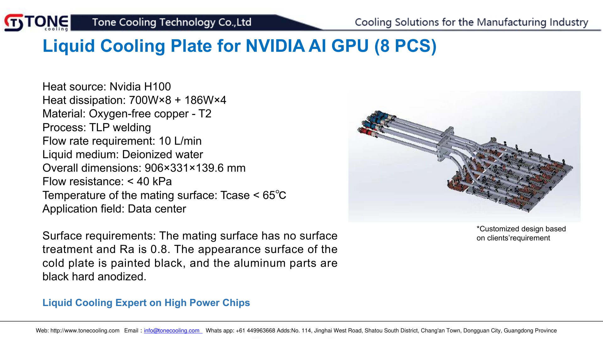
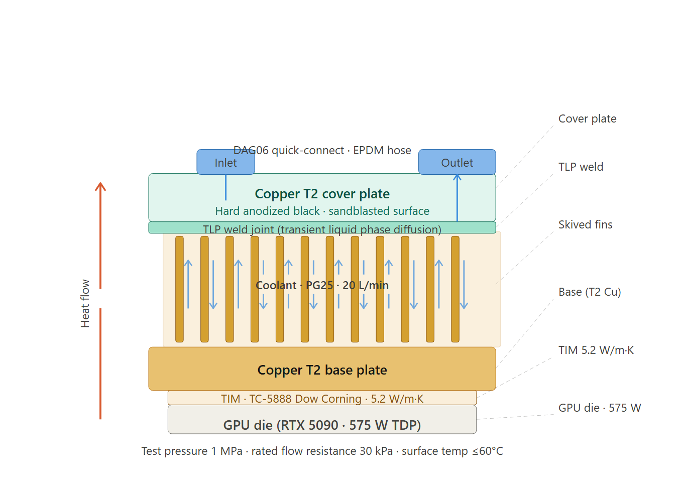
| Welding | TLP diffusion welding |
| Test pressure | 1 MPa (He leak + N₂ hold) |
| Coolant | PG25 (25% propylene glycol) |
| Custom design | Yes — DXF/STEP accepted |
Frequently Asked Questions — 3D Battery Cooling Plate
Does ToneCooling offer OEM and ODM services? — 3D Battery Cooling Plate
Yes. ToneCooling provides full OEM and ODM services including custom design, prototyping, thermal simulation, and volume production. We serve customers in North America, Europe, and Asia-Pacific with engineering support and samples within 2–4 weeks.
What materials are used in ToneCooling liquid cold plates? — 3D Battery Cooling Plate
ToneCooling manufactures cold plates in aluminum (6061/6063), copper (C1100/C1020), and stainless steel. Aluminum FSW cold plates are ideal for high-volume EV and industrial applications, while copper brazed cold plates provide maximum thermal conductivity (398 W/m·K) for high heat flux electronics.
What is the typical lead time for custom cold plates?
Prototype samples are delivered within 2–4 weeks. Production orders typically ship within 4–6 weeks after sample approval. ToneCooling responds to all quote requests within 24 business hours.
Get a Custom Thermal Solution from ToneCooling
ToneCooling is a professional liquid cooling solution provider specializing in custom cold plates, AIO coolers, and advanced thermal management systems. With ISO 9001:2015 certified manufacturing, we deliver prototype samples within 2–4 weeks. Contact ToneCooling today for a free consultation and quote — we respond within 24 business hours.
References: ASHRAE thermal standards, Wikipedia: Heat Sink Technology
Related ToneCooling Resources
- Liquid Cold Plates Product Line
- Request a Custom Cold Plate Quote
- Technical Resources & Design Guides
Need a Custom Liquid Cold Plate?
3D Battery Cooling Plate is a high-performance thermal management solution engineered by ToneCooling for demanding applications.
ToneCooling engineers design thermal solutions for your specific requirements. Get a detailed response within 24-48 hours.
Semiconductor Test Fixture Cold Plate is a critical component in modern thermal management. ToneCooling engineers this solution for AI servers, data centers, EV batteries, and power electronics requiring high-performance liquid cooling.
Semiconductor Test Fixture Cold Plate: Key Specifications
When evaluating semiconductor test fixture cold plate, engineers consider thermal resistance, pressure drop, flow rate, and material compatibility. ToneCooling provides detailed specs for every semiconductor test fixture cold plate design, backed by CFD simulation and testing.
Why Choose ToneCooling for Semiconductor Test Fixture Cold Plate
ToneCooling has manufactured over 50,000 semiconductor test fixture cold plate units for global OEM customers. Our semiconductor test fixture cold plate production features vacuum brazing furnaces below 10⁻⁴ mbar, FSW machines with ≤0.02mm flatness, and helium leak detection at 10⁻⁸ mbar·L/s. Every semiconductor test fixture cold plate undergoes 100% pressure testing at 25 bar.
Our engineering team provides free semiconductor test fixture cold plate design consultation, CFD simulation, and rapid prototyping in 7-14 days. Production semiconductor test fixture cold plate orders ship in 4-6 weeks under ISO 9001:2015 quality management.
Need a Custom Liquid Cold Plate?
ToneCooling engineers design thermal solutions for your requirements. Response within 24-48 hours.
Last Updated: 2026-04-08
DR Kevin, Thermal Engineer, ToneCooling