This guide on High-Density Liquid Cooling provides key insights for engineers and procurement teams. This comprehensive guide covers density liquid cooling solutions for industrial and OEM applications. ToneCooling provides expert insights on density liquid cooling technology and implementation.
The first section highlights the increasing demands placed on data centers and high-performance computing (HPC) systems, necessitating innovative thermal management solutions. As server density and power consumption continue to escalate, traditional air cooling methods struggle to maintain optimal operating temperatures, leading to performance degradation and potential hardware failure. A critical component often overlooked in cooling strategies for server systems is the dual in-line memory module (DIMM). Qi and Xiang have explored the thermal management of high-power memory modules in server platforms [1]. DIMMs, which are equipped with memory chips, generate substantial heat, thereby increasing the overall thermal load of the system. As DRAM technology has advanced from DDR3 to DDR5, power consumption has risen significantly. Typically, 15W is used as a benchmark to differentiate between standard DIMMs and high-power DIMMs. Insufficient cooling of DIMMs can result in thermal throttling, memory errors, and a reduced lifespan of the system. Je-Hyoung and Jae-Sang examined the thermal prediction of high-power memory modules, taking into account air speed, chip size, and power consumption [2]. Additionally, Son and Lho presented thermal analysis methods for forced air cooling solutions [3].
Before delving into new design concepts, let’s quickly review some key features of existing DIMM liquid cooling solutions to help readers understand their limitations and when alternative designs may be more appropriate. Currently, the industry primarily utilizes steel or copper tubes connected to cold plates for cooling DIMM components. Thermal Interface Materials (TIMs) are affixed to the surface of the tube body, facilitating heat transfer from the DIMM through direct contact. Figure 1 illustrates a DIMM liquid cooling tube solution currently available on the market, specifically referencing the Lenovo ThinkSystem SD650-N V2 server [1].
This design can enhance DIMM performance by reducing DIMM temperatures; however, it presents several deployment challenges due to certain limitations. **Compatibility and Cost:** The diversity of system layouts means that this design, which features fixed DIMM spacing, cannot be universally implemented as a standard component across different platforms, leading to increased overall costs. **Maintenance:** The DIMM liquid cooling system necessitates straightforward maintenance when inserting and removing DIMMs. The current design poses a risk of damaging the thermal interface material (TIM) on the surface of the tube during these operations. Additionally, there is a possibility of poor contact between the DIMM and the tube due to difficulties in controlling the contact force, which can result in uneven temperature distribution across the DIMMs. Reason: Improved clarity, vocabulary, and technical accuracy while maintaining the original meaning.

Part III: Modular Heat Sink and Cold Plate Design The primary objective of the modular heat sink and cold plate design is to ensure a stable contact force between the Dual In-line Memory Module (DIMM) and the heat sink. This stability is crucial for achieving a uniform temperature distribution within the DIMM and simplifying system maintenance. The design involves assembling the DIMM and heat sink separately, followed by inserting the DIMM module into the system. A pressure-providing clamp is then utilized to establish contact between the heat sink and the cold plate, facilitating an efficient heat transfer cycle from the DIMM assembly to the liquid. ### Reason: Improved clarity, vocabulary, and technical accuracy while maintaining the original meaning.

For DIMM liquid cooling solutions, the modular heat sink and cold plate design offers three primary advantages. First, the stable and uniform contact force provided by the clip ensures optimal contact between the DIMM, TIM1 (the thermal interface material between the DIMM and heat sink), and the heat sink itself. This configuration prevents uneven temperature distribution across the DIMM and enhances its heat dissipation performance. Second, the benchmark design for DIMM pitch is 0.297 inches, making it compatible with various DIMM pitch platform designs ranging from 0.297 to 0.35 inches. This versatility allows a single heat dissipation module to be utilized across multiple platforms, resulting in significant tooling cost savings. Third, by altering the heat sink material or design, the solution can be adapted to accommodate different DIMM thermal design power (TDP) requirements, aligning with both cost and performance objectives.
Part IV: Simulation and Test Results To demonstrate the advantages of a modular heat sink and cold plate design for a DIMM liquid cooling solution, thermal simulations were conducted using the Flotherm 2210 tool. This evaluation compared the thermal performance of the modular design with that of a traditional tube cold plate solution. The thermal model was established using a DDR5 Thermal Test Vehicle (TTV) for model correlation (see Figures 3 and 4 for detailed thermal model information). In the thermal simulation, only the thermal performance under ideal conditions was assessed to compare the differences between the two solutions. ### Reason: Improved clarity and readability by restructuring sentences, correcting punctuation, and enhancing vocabulary. Additionally, ensured technical accuracy by specifying


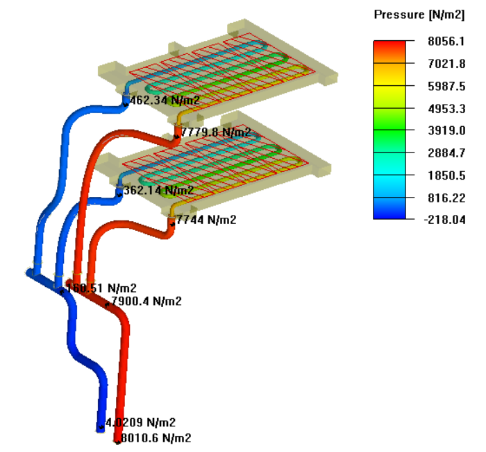
Since this solution utilizes a single-sided heat sink or pipe to contact the DIMM assembly, the opposite side of the DIMM assembly consistently represents the worst-case scenario in both DIMM liquid cooling solutions. Under identical boundary conditions, the liquid flow rate is assumed to be 1 liter per minute (LPM) per loop, and the temperature of the liquid flow adheres to ASHRAE W45 as the thermal boundary conditions for the simulation. The pipe solution features sub-channels, resulting in a lower flow rate per DIMM compared to the modular heat sink and cold plate solutions. Figure 5 illustrates the differences in liquid flow distribution among these concepts.

According to the TTV test results, the outcomes differ from the simulation results by approximately 5%. Regardless of the test or thermal model simulation, the modular heat sink and cold plate solution consistently demonstrate lower thermal resistance, showing an improvement of 8% to 19% based on a single prototype test result. Taking into account the variation among the prototype samples, this result is the closest to the average value.

Functional DIMMs consist of various components, including DRAM, buffers, registers, PMIC, and SPD. Among these, DRAM is the primary bottleneck in DIMMs due to its lower temperature specification compared to the other components. Simulation results indicate that DRAM positioned in the central area of the air side experiences the most severe conditions. This is attributed to the self-heating of the DRAM and the cross-heating effects from higher power components, causing it to reach the temperature limit first.
The surface temperature distribution of the heat sink is illustrated in Figure 7 below. The overall temperature distribution across the heat sink and the DIMM contact surface is approximately 7 to 8°C. The center temperature of all DRAM packages is monitored, and the highest recorded temperature is reported. Figure 8 displays the temperature distribution on both sides of the DIMM. The temperature on the side of the DIMM that is not in contact with the heat sink is higher, as it is based on a pure liquid cooling simulation with no airflow through the DIMM area. To further enhance DIMM performance, it is advisable to consider employing a heat sink that contacts the DIMM on both sides, ensuring a minimal temperature difference across the DIMM.
The modular heat sink and cold plate solution has been prototyped and validated with DDR5 TTV. It is now co-designed and integrated into IEIT’s comprehensive liquid cooling solution. Figure 9 illustrates the modular DIMM liquid cooling solution featuring four half-width node systems within a 2U server. However, this cooling solution is versatile and can be applied to various systems and board layouts. The cold plate depicted in Figure 4 can be extended or shortened to accommodate different numbers of DIMMs. In an extended core system with additional DIMM slots, more individual DIMM heat sinks can be assembled onto the cold plate. With its flexible design, the modular heat sink and cold plate solution can be adapted to systems with diverse layouts and form factors.

The IEIT liquid cooling system employs a dual CPU shadow core layout, with each CPU featuring eight Samsung 64GB 4800MHz DDR5 DIMMs. Preliminary test data (see Table 1: IEIT Liquid Cooling System DIMM Performance) indicates that the DIMMs possess adequate thermal margins, which suggest their capability to support higher thermal design power (TDP) levels consistent with the simulation results.

### **Section V Summary** To address the continuous cooling requirements associated with memory power consumption, this paper proposes a novel liquid-cooled memory solution. The module has been patented across multiple concepts, overcoming the cooling limitations of existing memory liquid cooling systems. The thermal performance of the proposed solution is enhanced by 8% to 19% compared to traditional memory cooling plate tube solutions. A thermal analysis based on the DDR5 memory thermal model is conducted to demonstrate the cooling capability of the proposed solution. A prototype has been designed to validate the concept and assess whether the cooling capability targets can be achieved. Test data indicates that the discrepancy between the test results and simulations, based on the TTV test outcomes, is within 5%. Furthermore, the modular memory cooling plate solution has been integrated into a functional system to confirm that the design objectives yield superior performance. As a next step, further research is planned to enhance the design and performance to accommodate higher TDP DIMMs in accordance with the DIMM roadmap. ### Reason: Improved clarity, vocabulary, and technical accuracy while correcting grammatical and punctuation errors.
Source: Mai Mai Re Design
For industry standards and best practices, refer to ASHRAE thermal guidelines.
What Is High Density Liquid Cooling?
Does ToneCooling offer OEM and ODM services? — High-Density Liquid Cooling
Yes. ToneCooling provides full OEM and ODM services including custom design, prototyping, thermal simulation, and volume production. We serve customers in North America, Europe, and Asia-Pacific with engineering support and samples within 2–4 weeks.
What materials are used in ToneCooling liquid cold plates? — High-Density Liquid Cooling
ToneCooling manufactures cold plates in aluminum (6061/6063), copper (C1100/C1020), and stainless steel. Aluminum FSW cold plates are ideal for high-volume EV and industrial applications, while copper brazed cold plates provide maximum thermal conductivity (398 W/m·K) for high heat flux electronics.
What is the typical lead time for custom cold plates?
Prototype samples are delivered within 2–4 weeks. Production orders typically ship within 4–6 weeks after sample approval. ToneCooling responds to all quote requests within 24 business hours.
Get a Custom Thermal Solution from ToneCooling
ToneCooling is a professional liquid cooling solution provider specializing in custom cold plates, AIO coolers, and advanced thermal management systems. With ISO 9001:2015 certified manufacturing, we deliver prototype samples within 2–4 weeks. Contact ToneCooling today for a free consultation and quote — we respond within 24 business hours.
Related ToneCooling Resources
- Liquid Cold Plates Product Line
- Request a Custom Cold Plate Quote
- Technical Resources & Design Guides
Industry References & Standards
Need a Custom Liquid Cold Plate?
High Density Liquid Cooling is a high-performance thermal management solution engineered by ToneCooling for demanding applications.
ToneCooling engineers design thermal solutions for your specific requirements. Get a detailed response within 24-48 hours.
Density Liquid Cooling Solutions: Key Specifications
When evaluating density liquid cooling solutions, engineers consider thermal resistance, pressure drop, flow rate, and material compatibility. ToneCooling provides detailed specs for every density liquid cooling solutions design, backed by CFD simulation and testing.
| Parameter | ToneCooling Specification |
|---|---|
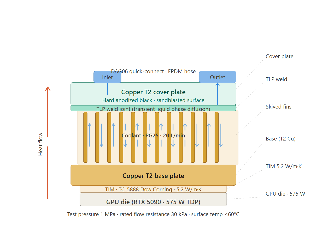
| Material | Copper T2 / 6061 aluminum |
| Welding | TLP diffusion welding |
| Test pressure | 1 MPa (He leak + N₂ hold) |
| Coolant | PG25 (25% propylene glycol) |
| Custom design | Yes — DXF/STEP accepted |
Why Choose ToneCooling for Density Liquid Cooling Solutions
ToneCooling has manufactured over 50,000 density liquid cooling solutions units for global OEM customers. Our density liquid cooling solutions production features vacuum brazing furnaces below 10⁻⁴ mbar, FSW machines with ≤0.02mm flatness, and helium leak detection at 10⁻⁸ mbar·L/s. Every density liquid cooling solutions undergoes 100% pressure testing at 25 bar.
Our engineering team provides free density liquid cooling solutions design consultation, CFD simulation, and rapid prototyping in 7-14 days. Production density liquid cooling solutions orders ship in 4-6 weeks under ISO 9001:2015 quality management.
Need a Custom Liquid Cold Plate?
ToneCooling engineers design thermal solutions for your requirements. Response within 24-48 hours.
Last Updated: 2026-04-08
DR Kevin, Thermal Engineer, ToneCooling