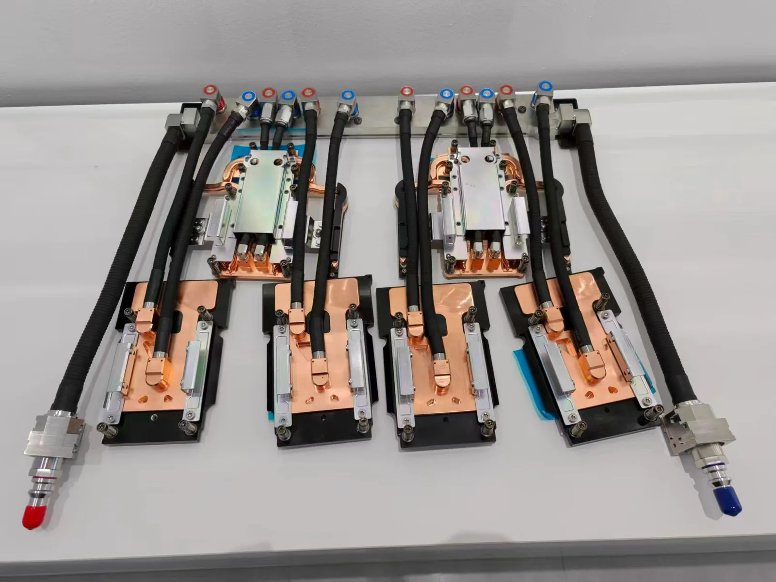
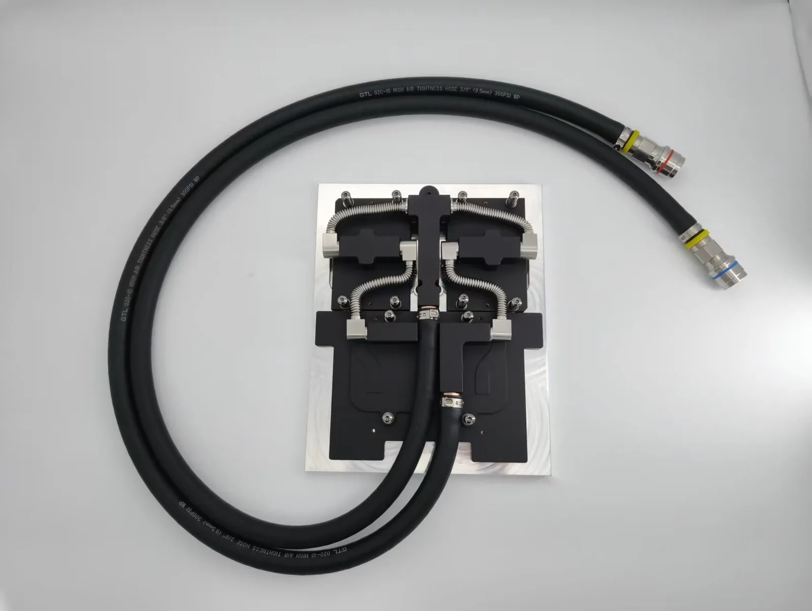
Overview
Immersion liquid cooling represents the next frontier in data center thermal management. Unlike traditional direct-to-chip systems that use water-glycol coolant in a closed loop, immersion blade servers submerge entire computing blades in dielectric coolant — requiring fundamentally different cold plate design approaches.
The inline blade configuration presents unique challenges: multiple chips of varying power densities (from 5W auxiliary components to 245W main processors) share a single cold plate within a compact blade form factor. Computational Fluid Dynamics (CFD) simulation is essential to validate that every chip stays within its thermal specification before committing to manufacturing.
This article presents ToneCooling’s verified CFD simulation results for an immersion inline blade server liquid cold plate, demonstrating thermal performance across 13 chips with a total power dissipation of 325W.
Blade Server Structure and Chip Layout
The inline blade server features a compact rectangular form factor designed for vertical insertion into immersion cooling tanks. The blade houses a complex multi-chip arrangement on a single PCB, with components ranging from low-power auxiliary ICs to a high-power main processor.

The chip layout includes three distinct power tiers mounted on the blade PCB:
| Chip Group | Quantity | Power per Chip | Total Power |
|---|---|---|---|
| Auxiliary ICs | 10 | 5W | 50W |
| Mid-Power Chips | 2 | 15W | 30W |
| Main Processor | 1 | 245.1W | 245.1W |
| Total | 13 | — | 325.1W |

The main 245.1W processor dominates the thermal load, accounting for 75% of the total blade power. The cold plate design must provide adequate cooling to this high-density zone while also managing the distributed heat from 12 smaller components across the PCB area.
Liquid Cold Plate Design: AL3003 Aluminum
The liquid cold plate is manufactured from AL3003 aluminum alloy, selected for its combination of good thermal conductivity, excellent corrosion resistance in dielectric fluid environments, and cost-effectiveness for volume production. The cold plate geometry is precision-machined to match the blade PCB footprint with recessed mounting pockets for each chip group.

Key cold plate design features include:
- Material: AL3003 aluminum alloy — optimized for dielectric coolant compatibility
- Thermal interface: 0.2mm thermal pad with 5 W/m·K conductivity between chips and cold plate
- Internal channels: Precision-machined flow passages sized for 4 L/min dielectric coolant flow
- Mounting: Direct contact via thermal pad to each chip location on the PCB
Simulation Parameters and Dielectric Coolant Properties
The CFD analysis uses boundary conditions representative of a production immersion cooling deployment. The dielectric coolant is a fluorinated fluid with properties optimized for single-phase immersion cooling of electronics.
| Parameter | Value |
|---|---|
| Ambient Temperature | 25°C |
| Coolant Type | Dielectric fluorinated fluid |
| Inlet Temperature | 25°C |
| Flow Rate | 4 L/min |
| Thermal Pad Conductivity | 5 W/m·K (thickness 0.2mm) |
| Cold Plate Material | AL3003 aluminum |
| Total Power Dissipation | 325.1W (13 chips) |
Dielectric coolant properties used in the simulation:
| Property | Value |
|---|---|
| Pour Point | -55°C |
| Kinematic Viscosity (40°C) | 40 mm²/s |
| Density (20°C) | 980 kg/m³ |
| Specific Heat (40°C) | 1.5 J/g·K |
| Thermal Conductivity | 0.15 W/m·K |
| Dielectric Strength | 50 kV |
| Flash Point | 300°C |
| Fire Point | 350°C |
The dielectric coolant’s low thermal conductivity (0.15 W/m·K vs. 0.6 W/m·K for water) means the cold plate internal channel design must compensate with higher surface area and optimized flow distribution. However, the fluid’s excellent dielectric properties (50kV breakdown voltage) and wide temperature range (-55°C to 300°C+) make it ideal for immersion applications where electronics are directly submerged.
CFD Simulation Results: Chip Temperature Distribution
The simulation results confirm that all 13 chips remain well within safe operating temperatures. The thermal performance breakdown by chip group:
| Chip Group | Power | Max Temperature | Margin to 85°C |
|---|---|---|---|
| Main Processor (245.1W) | 245.1W | 50.80°C | 34.2°C |
| 5W Auxiliary ICs (×10) | 5W each | 53.7°C | 31.3°C |
| 15W Mid-Power Chips (×2) | 15W each | 54.15°C | 30.85°C |

A notable finding: the 245.1W main processor runs cooler (50.80°C) than the smaller 5W and 15W chips (53.7–54.15°C). This is because the cold plate flow channel design concentrates cooling capacity directly under the main processor die area, with dedicated high-velocity flow passages. The smaller chips, despite their lower individual power, have less direct contact with the primary coolant flow path.
Detailed simulation data for individual monitoring points:
| Component | Type | Average Temperature |
|---|---|---|
| 245.1W Main Processor | Solid surface | 50.706°C |
| 15W Chip #1 | Solid surface | 52.961°C |
| 16W Chip | Solid surface | 35.108°C |
| 25W Chip | Solid surface | 35.840°C |
| 40W Chip | Solid surface | 37.972°C |
| 8W Chip | Solid surface | 34.497°C |
| 8W Chip #1 | Solid surface | 33.666°C |
| 8W Chip #2 | Solid surface | 34.013°C |
| 3W Chip | Solid surface | 32.023°C |
| 5W Chip | Solid surface | 33.815°C (avg) |
Cold Plate Surface Temperature Distribution
The cold plate surface temperature cloud map reveals the thermal gradient across the AL3003 plate:

- Maximum solid temperature: 55.049°C (directly above the 245.1W processor)
- Average solid temperature: 33.815°C across the full cold plate surface
- Coolant inlet temperature: 25°C
- Coolant outlet temperature: 29.349°C (ΔT = 4.35°C)
- Maximum coolant temperature: 55.049°C (localized near processor zone)
- Average coolant velocity: 0.021 m/s
- Maximum coolant velocity: 3.273 m/s (at channel restrictions)
- Maximum pressure: 30,661 Pa (0.31 bar)
- Average pressure: 57.277 Pa
- Total convective heat transfer: 440.96W

The low coolant ΔT of only 4.35°C indicates that the 4 L/min flow rate provides more than adequate thermal capacity for the 325W total blade power. The cold plate’s convective heat transfer of 440.96W exceeds the total chip power, confirming effective heat removal including secondary thermal paths through the PCB substrate.
Key Engineering Takeaways for Immersion Blade Cold Plate Design
This CFD validation reveals several important design principles for immersion blade server liquid cold plates:
- Dedicated flow paths for high-power zones: The 245.1W processor achieves better thermal performance (50.8°C) than much smaller chips because of concentrated flow channel design directly under the die. Channel geometry matters more than raw power density.
- Dielectric coolant thermal conductivity compensation: With only 0.15 W/m·K (vs. water’s 0.6 W/m·K), dielectric fluids require 3–4× more internal surface area in the cold plate to achieve equivalent thermal resistance. This drives the need for precision-machined micro-features.
- Low pressure drop advantage: The maximum system pressure of 30.7 kPa (0.31 bar) at 4 L/min flow rate keeps pump power requirements minimal — critical for immersion systems where the pump must also circulate fluid through the immersion tank.
- Uniform thermal interface is essential: The 0.2mm thermal pad at 5 W/m·K represents a significant thermal resistance layer. Reducing pad thickness to 0.1mm or using higher-conductivity interface materials (10+ W/m·K) could reduce chip temperatures by an additional 3–5°C.
- AL3003 aluminum is well-suited for dielectric coolant: Unlike water-glycol systems that can cause galvanic corrosion with aluminum, dielectric fluorinated fluids are chemically inert, making AL3003 an excellent choice for long-term reliability in immersion environments.
Frequently Asked Questions
Why does the 245W main chip run cooler than 5W auxiliary chips?
The cold plate’s internal flow channels are specifically designed to concentrate coolant flow under the main processor die area. This creates a higher local heat transfer coefficient at the main chip location. The 5W chips, positioned away from primary flow paths, have less direct coolant contact and therefore run slightly warmer despite their much lower power. This is a deliberate design trade-off that optimizes cooling where it matters most.
What is the maximum blade power this cold plate design can handle?
With all chips currently below 55°C and an 85°C thermal throttling threshold, there is approximately 30°C of thermal margin. Scaling linearly, the cold plate could handle roughly 500–600W total blade power at the same 4 L/min flow rate before any chip approaches thermal limits. Increasing flow rate to 6–8 L/min would extend this further.
Can this cold plate design be adapted for two-phase immersion cooling?
This simulation models single-phase immersion cooling where the dielectric fluid remains liquid throughout. For two-phase immersion systems (where the fluid boils at chip surfaces), the cold plate design would require modifications to accommodate vapor management and condensation. ToneCooling offers both single-phase and two-phase immersion cold plate designs — contact our engineering team for project-specific recommendations.
Need a Custom Immersion Cold Plate for Your Blade Server?
ToneCooling manufactures custom liquid cold plates for immersion cooling applications including blade servers, GPU accelerators, and high-density computing modules. Our capabilities include:
- CFD thermal simulation and design validation before manufacturing
- AL3003, AL6061, and copper cold plate options
- Compatibility with all major dielectric coolant brands
- prototypes from 1 piece — prototype in 4–6 weeks
Request RFQ | AI Server Liquid Cooling Solutions | Custom Liquid Cold Plates
Related ToneCooling Resources
Industry References & Standards
Why Choose ToneCooling for Liquid Cold Plate Cfd Simulation
Engineering review and prototype planning are based on the project requirements. Custom prototype lead time is normally 4–6 weeks after drawing approval and order confirmation; confirm the production schedule in the quotation.
Last Updated: 2026-04-08