This comprehensive guide covers precision load plates solutions for industrial and OEM applications. ToneCooling provides expert insights on precision load plates technology and implementation.
±0.001 mm flatness, low CTE Invar, durable hard-gold plating—stable probes, higher yield, lower downtime
Semiconductor Test Fixtures: An In-Depth Analysis of High-Performance Load Plates to Enhance Chip Test Efficiency and Yield
Introduction: The Unsung Hero of the Test Process — Precision load plates

In the pyramid of semiconductor manufacturing, front-end processes (wafer fabrication) are akin to meticulous creation, while back-end processes (packaging and testing) serve as the critical quality checkpoints that ensure every “artifact” can withstand scrutiny. Among these, chip testing (CP, FT, SLT) is the core defense line for cost control, quality assurance, and brand reputation.
For semiconductor equipment engineers who work with precision machinery daily, our focus often lies on the expensive testers, probe stations, and handlers themselves, while overlooking a seemingly simple yet crucial component—the Load Plate (or Socket Plate). It sits quietly fixed within the test socket, cradding invaluable chips, acting as the final interface for signal, power, and mechanical force transmission. A high-performance load plate is far from an ordinary metal plate; it is a masterpiece integrating precision mechanics, materials science, and electrical design—the unsung hero in enhancing test efficiency and yield.
This article provides an in-depth analysis of the design essence, material secrets, and selection strategies for high-performance load plates, offering a comprehensive technical reference for semiconductor equipment engineers.
Chapter 1: Why are High-Performance Load Plates Critical?—The Dual Challenges of Efficiency and Yield
Before discussing the “how,” we must understand the “why.” A substandard or mismatched load plate can trigger a cascade of problems, directly impacting the KPIs of the test floor.
- Test Yield Distortion:
- Unstable Contact Resistance: Poor flatness, worn or oxidized surface plating of the load plate can increase and fluctuate contact resistance with the probes. This introduces additional voltage drops and thermal noise, causing power supply tests (Iddq), leakage tests, and high-speed digital test results to drift, leading to good chips being falsely rejected (False Reject) and directly lowering the final yield.
- Degraded Signal Integrity: In high-frequency applications (e.g., RF chips, high-speed SerDes testing), the dielectric constant (Dk) and dissipation factor (Df) of the load plate are crucial. Inappropriate materials can absorb signal energy, causing attenuation, reflection, and crosstalk, resulting in eye diagram closure and increased jitter, preventing accurate assessment of the chip’s true performance.
- Low Test Efficiency:
- Increased Downtime: Load plates require regular cleaning and maintenance. Designs with low durability wear out quickly, and plating easily peels off, forcing frequent production line stoppages for replacement or maintenance, severely reducing Overall Equipment Effectiveness (OEE).
- Prolonged Calibration and Debugging Time: Test instability caused by the load plate can lead engineers to spend excessive time on debugging and retesting, preventing rapid establishment of a stable mass production test rhythm.
- High Total Cost of Ownership (TCO):
- Frequently replacing cheap but fragile load plates accumulates costs far exceeding a one-time investment in a high-performance, long-life product. This doesn’t even account for the immense hidden costs of downtime and quality issues.
For equipment engineers, selecting a load plate is essentially an investment in stability, an investment in efficiency, and an investment in yield.
Chapter 2: Dissecting the High-Performance Load Plate: Core Design and Material Technology
How is a high-performance load plate engineered? Let’s analyze its core elements one by one.
1. Materials Science and Thermal Management
- Base Material Selection:
- Invar: An iron-nickel alloy renowned for its extremely low coefficient of thermal expansion (CTE). When the chip and fixture heat up due to power cycling during testing, an Invar load plate minimizes dimensional change, ensuring probe tips remain aligned with the pad centers, avoiding contact issues or pad damage caused by thermal drift. This is the First choice for high-precision, high-power testing.
- Titanium Alloy: Offers high strength, low weight, and excellent corrosion resistance. Its CTE, while higher than Invar’s, is much lower than aluminum’s, making it a good compromise for weight-sensitive applications (e.g., gravity-contact testing).
- Stainless Steel: Provides good mechanical strength and corrosion resistance at a higher cost-effectiveness, suitable for many standard test scenarios.
- Engineering Plastics (PEEK, VESPEL): Used for high-frequency/RF tests requiring extreme insulation or very low dielectric loss. They minimize signal leakage and interference.
- Thermal Management Design:
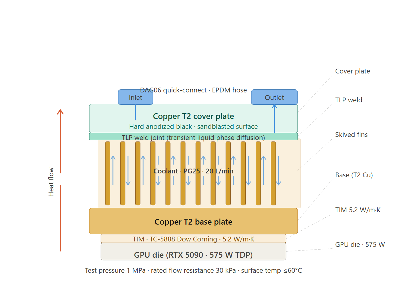
- High-performance load plates may integrate cooling channels allowing coolant to flow through, actively removing heat generated by the test chip, maintaining a controlled junction temperature for accurate performance testing.
- Surfaces may undergo treatments like black anodization to enhance thermal radiation and aid heat dissipation.
2. Precision Machining and Flatness
The absolute flatness of the load plate is fundamental to ensuring all probes contact the chip pads simultaneously, with equal pressure and engagement.
- Machining Precision: Utilizes high-precision CNC milling and grinding machines, ensuring flatness is typically controlled within ±0.001mm to ±0.005mm.
- Stress Relief: Materials develop internal stresses after machining, which can cause micro-deformation over time. Superior manufacturers perform multiple aging treatments and stress relief processes to ensure long-term dimensional stability of the delivered product.
3. Surface Treatment and Plating Technology
This is the interface that directly contacts the probes, and its importance cannot be overstated.
- Plating Material: Hard gold is the standard choice. Its thickness (typically 30-50 microinches) and hardness are critical, striking the optimal balance between wear resistance (longevity) and excellent conductivity.
- Underplating: A nickel layer is usually applied beneath the gold layer. Nickel acts as a barrier, preventing diffusion between the base material (e.g., copper) and gold, while providing support and enhancing the wear resistance of the gold layer.
- Surface Finish: A very low surface roughness (Ra) reduces friction with probes, decreases wear, and ensures stable contact resistance.
4. Customized Design for Specific Applications
- Apertures and Cavity Design: Must perfectly match the chip size, probe card, or socket type, providing precise space for probe movement, chip placement, and heat dissipation.
- Mounting and Alignment Features: Integrate precise dowel pins, screw holes, ensuring quick, accurate, and repeatable installation onto the test socket.
- RF/High-Frequency Optimization: For radio frequency chips, designs may include grounding vias, shielded cavities, or even layered composite materials to control impedance and reduce signal loss.
Chapter 3: Practical Guide: How Semiconductor Equipment Engineers Select and Maintain?
Theory must ultimately serve practice. Here are specific recommendations for equipment engineers.
1. Load Plate Selection Checklist:
- Application Scenario: CP (Wafer Test), FT (Final Test), or SLT (System Level Test)?
- Chip Type: Digital, Analog, Mixed-Signal, RF, or High-Power?
- Test Frequency/Speed: Is low Dk/Df material required?
- Thermal Budget: What is the chip’s power consumption? Is integrated active cooling needed?
- Mechanical Interface: Must be 100% compatible with existing test socket, handler, or prober models.
- Flatness and Tolerances: Refer to the equipment manufacturer’s requirements, often explicitly stated in the specifications.
- Plating Specifications: Clearly require the type, thickness, and hardness of the gold plating.
- Supplier Qualifications: Choose suppliers with ISO certification, extensive industry experience, and a sound quality system. Request material certification reports and precision inspection reports.
2. Daily Maintenance and Troubleshooting:
- Regular Cleaning: Gently wipe the surface with a lint-free cloth dipped in a dedicated electronic-grade cleaner (e.g., IPA) to remove oxides, dust, and organic contaminants. Avoid abrasive materials.
- Regular Inspection:
- Visual Inspection: Observe the surface plating under a microscope for wear, scratches, corrosion, or stains.
- Flatness Check: Perform periodic spot checks using a dial indicator or optical flatness tester.
- Contact Resistance Check: Monitor resistance value changes at representative points using the four-wire method.
- Establish Lifecycle Records: Maintain records for each load plate detailing its usage count, maintenance history, and performance, enabling predictive maintenance and planning replacement before performance degrades.
- Common Issues and Countermeasures:
- Sudden Test Yield Drop: First, check the load plate surface cleanliness and plating condition.
- Unstable Contact: Check if flatness has been compromised due to external force or thermal stress.
- High-Frequency Test Failure: Suspect unsuitable material dielectric properties or design.
Chapter 4: Future Trends: Meeting the Challenges of Advanced Packaging
As semiconductors enter the era of heterogeneous integration and advanced packaging, chip testing faces new challenges, and load plates must evolve accordingly.
- 2.5D/3D IC Testing: Chip stacking and Through-Silicon Vias (TSVs) require test interfaces to handle more complex spatial structures and higher power densities. Load plates may require more complex designs like multi-layer structures and micro-channel cooling.
- Smaller Size, Higher Density: Continually shrinking chip pad pitches demand near-苛刻 requirements for load plate machining accuracy and flatness.
- Higher Frequencies: 5G-Advanced and 6G technologies will push testing frequencies into higher bands, making the demand for low-loss materials standard.
- Intelligence and Datafication: In the future, “smart load plates” integrated with micro-sensors (temperature, pressure) might become feasible, monitoring the test interface status in real-time, providing data support for predictive maintenance and intelligent testing.
Conclusion: The Devil is in the Details
In the world of semiconductor testing, which pursues ultimate efficiency and yield, a Disadvantages in any link can dilute the efforts of all cutting-edge technologies. The high-performance load plate, this seemingly ordinary fixture component, is actually the cornerstone of precision, reliability, and stability.
For semiconductor equipment engineers, deeply understanding the technical principles behind it, making scientific selection decisions, and implementing rigorous maintenance procedures are not trivial tasks. Instead, they are key professional skills that ensure the efficient and reliable operation of the test line, ultimately contributing to corporate cost reduction, efficiency improvement, and enhanced competitiveness. The devil is in the details, and it is precisely on these seemingly inconspicuous components that the professionalism and value of an engineer are most evident.

For industry standards and best practices, refer to ASHRAE thermal guidelines.
What Is High Precision Load Plates?
Does ToneCooling offer OEM and ODM services? — Precision load plates
Yes. ToneCooling provides full OEM and ODM services including custom design, prototyping, thermal simulation, and volume production. We serve customers in North America, Europe, and Asia-Pacific with engineering support and samples within 2–4 weeks.
What industries does ToneCooling serve?
ToneCooling serves data center, telecommunications, EV/automotive, power electronics, aerospace, medical devices, and industrial laser markets with custom thermal management solutions.
How can I get a quote from ToneCooling?
Visit tonecooling.com/contact or email info@tonecooling.com with your thermal requirements. ToneCooling responds to all inquiries within 24 business hours.
Get a Custom Thermal Solution from ToneCooling
ToneCooling is a professional liquid cooling solution provider specializing in custom cold plates, AIO coolers, and advanced thermal management systems. With ISO 9001:2015 certified manufacturing, we deliver prototype samples within 2–4 weeks. Contact ToneCooling today for a free consultation and quote — we respond within 24 business hours.
For industry standards and best practices, refer to ASHRAE thermal guidelines.
| Parameter | ToneCooling Specification |
|---|---|
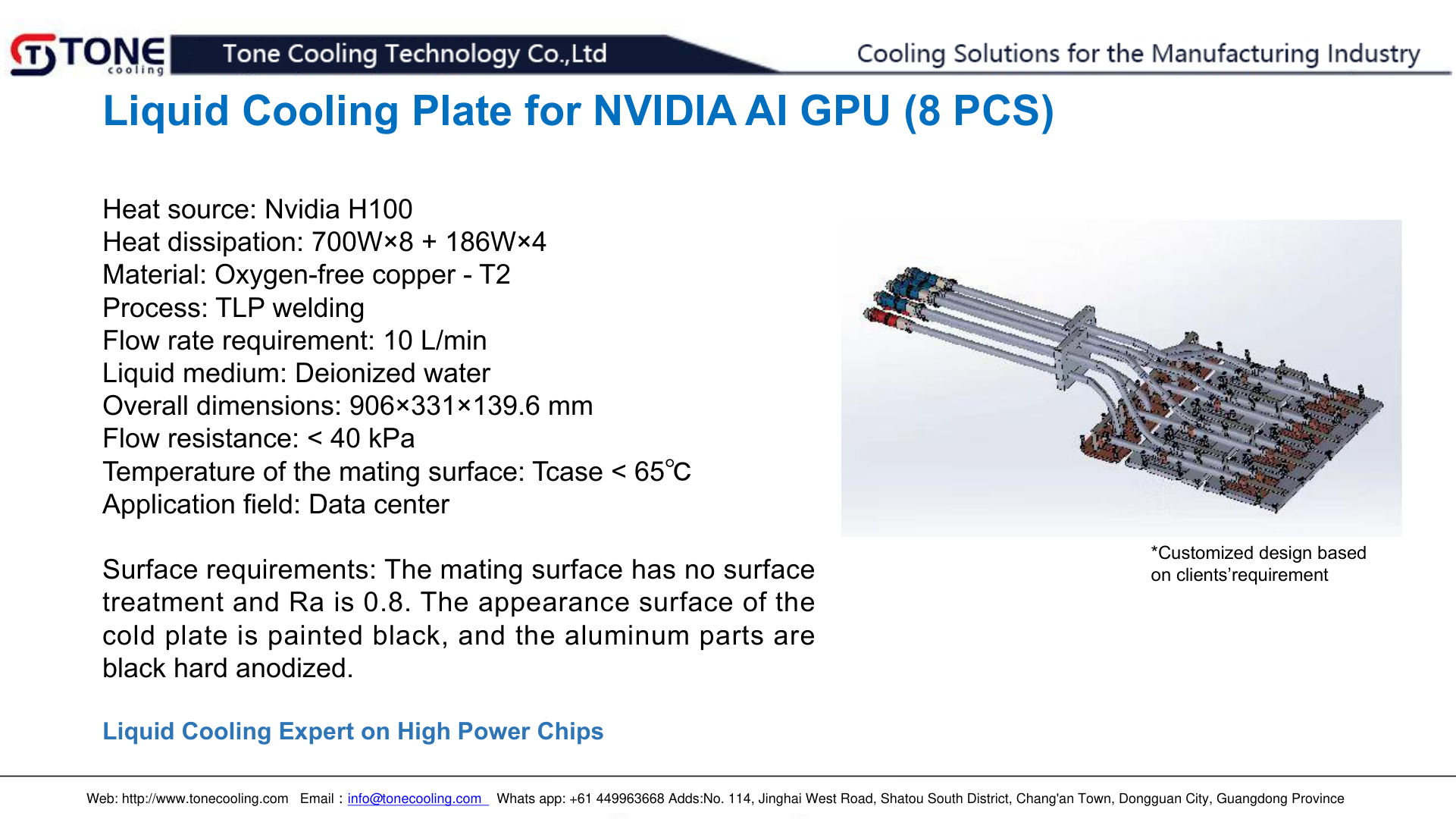
| Material | Copper T2 / 6061 aluminum |
| Welding method | Transient liquid phase diffusion welding |
| Test pressure | 1 MPa (helium leak + nitrogen hold) |
| Working medium | PG25 (25% propylene glycol) |
| Custom design | Yes — DXF/STEP input accepted |
Frequently Asked Questions
Does ToneCooling offer OEM and ODM services?
Yes. ToneCooling provides full OEM and ODM services including custom design, prototyping, thermal simulation, and volume production. We serve customers in North America, Europe, and Asia-Pacific with engineering support and samples within 2–4 weeks.
What industries does ToneCooling serve?
ToneCooling serves data center, telecommunications, EV/automotive, power electronics, aerospace, medical devices, and industrial laser markets with custom thermal management solutions.
How can I get a quote from ToneCooling?
Visit tonecooling.com/contact or email info@tonecooling.com with your thermal requirements. ToneCooling responds to all inquiries within 24 business hours.
Get a Custom Thermal Solution from ToneCooling
ToneCooling is a professional liquid cooling solution provider specializing in custom cold plates, AIO coolers, and advanced thermal management systems. With ISO 9001:2015 certified manufacturing, we deliver prototype samples within 2–4 weeks. Contact ToneCooling today for a free consultation and quote — we respond within 24 business hours.
High Precision Load Plates is a high-performance thermal management solution engineered by ToneCooling for demanding applications.
Semiconductor Test Fixture Cold Plate is a critical component in modern thermal management. ToneCooling engineers this solution for AI servers, data centers, EV batteries, and power electronics requiring high-performance liquid cooling.
Semiconductor Test Fixture Cold Plate: Key Specifications
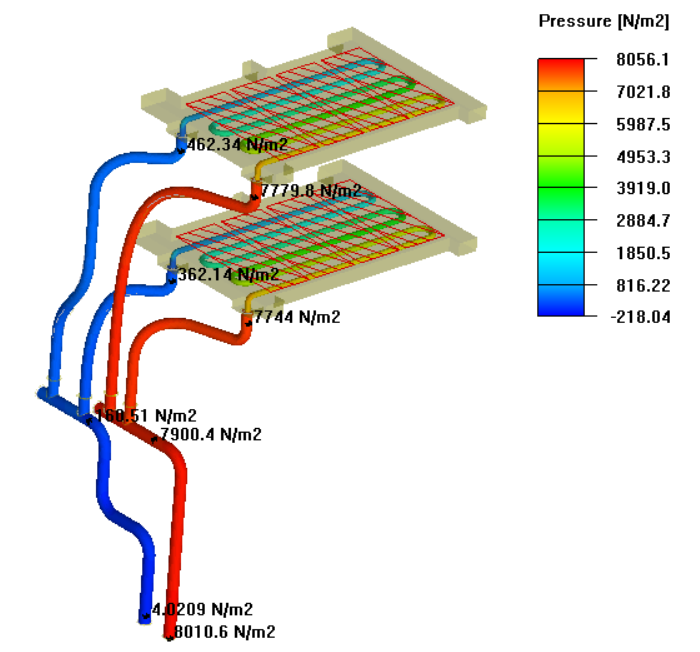
When evaluating semiconductor test fixture cold plate, engineers consider thermal resistance, pressure drop, flow rate, and material compatibility. ToneCooling provides detailed specs for every semiconductor test fixture cold plate design, backed by CFD simulation and testing.
Why Choose ToneCooling for Semiconductor Test Fixture Cold Plate
ToneCooling has manufactured over 50,000 semiconductor test fixture cold plate units for global OEM customers. Our semiconductor test fixture cold plate production features vacuum brazing furnaces below 10⁻⁴ mbar, FSW machines with ≤0.02mm flatness, and helium leak detection at 10⁻⁸ mbar·L/s. Every semiconductor test fixture cold plate undergoes 100% pressure testing at 25 bar.
Our engineering team provides free semiconductor test fixture cold plate design consultation, CFD simulation, and rapid prototyping in 7-14 days. Production semiconductor test fixture cold plate orders ship in 4-6 weeks under ISO 9001:2015 quality management.
Last Updated: 2026-04-08
DR Kevin, Thermal Engineer, ToneCooling
Need a custom high precision load plates solution?
ToneCooling engineers respond within 24 hours with CFD-validated thermal recommendations.
References: ISO 9001
Need a Custom Liquid Cold Plate?
Tell us your thermal requirements. Engineering team responds within 48 hours with design proposal and quotation.
Request a Quote →MOQ 5 pcs • Prototype 7-15 days • ISO 9001 Certified