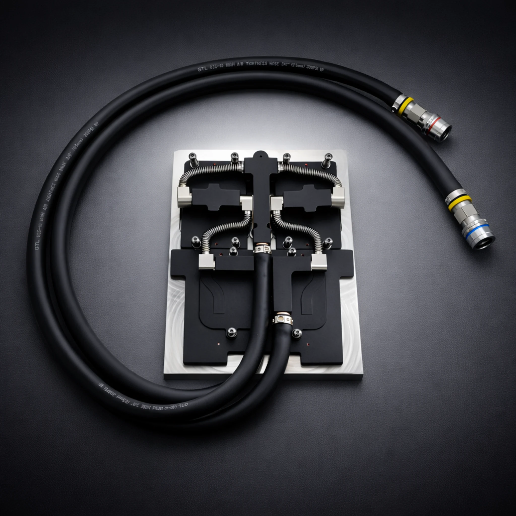
This comprehensive guide covers cold plates positioning and solutions for industrial and OEM applications. ToneCooling provides expert insights on cold plates positioning and technology and implementation.
Optimal placement of cold plates maximizes cooling efficiency by targeting high heat flux zones and ensuring proper fluid flow. Correct positioning can improve reliability by up to 31% and reduce humidity-related issues by 50%, according to recent studies. Critical factors include a level surface, absence of obstructions, minimal exposure to sunlight, and proper alignment with system components.
This article explores where cold plates are typically positioned within systems and why placement plays a critical role in thermal performance.

What Is Cold Plates Positioning Placement?
Surface Level and Stability — Cold plates positioning and
A flat and stable surface ensures maximum contact between the cold plate and the heat source. Surface flatness should not vary more than 0.001 inch per inch to achieve optimal heat transfer. Warped or uneven surfaces reduce efficiency and can cause leaks. For thin plates, designers must balance flatness with cost and structural strength. Hydraulic pressing and skim cutting help achieve the required flatness, but care is needed to avoid weakening the plate.
Avoiding Obstructions and Heat Sources — Cold plates positioning and
Obstructions near cold plates block airflow and reduce cooling performance. Placing cold plates away from direct sunlight and other heat sources prevents unwanted heat gain. Environmental factors like ambient temperature and spatial constraints also affect placement. In industrial settings, the location of the heat source and system integration play a key role in deciding where to install cold plates.
- Keep the area around the cold plate clear for unobstructed airflow.
- Avoid placing cold plates near equipment that generates extra heat.
Inlet and Outlet Orientation
The orientation of inlet and outlet ports controls coolant flow and temperature uniformity. Vertical arrangements, such as upflow or downflow, provide better temperature balance and vapor removal. Horizontal flows can cause uneven heat transfer due to vapor buildup.
Using multiple inlets and outlets along the width reduces pressure drop and improves heat removal. Arrangements like L-shaped or staggered vertical layouts further enhance performance by lowering thermal resistance and temperature gradients.
- Arrange inlets and outlets to minimize pressure drop and maximize heat transfer.
- Use multiple ports when possible to improve flow distribution.
Component Alignment
Precise alignment of cold plates with system components ensures effective heat transfer. Calibration tools help align the cold plate with reference points in high-density assemblies. Virtual and physical simulations validate the setup and reduce errors. Proper alignment also prevents misplacement and improves repeatability in installation.
Installation Steps
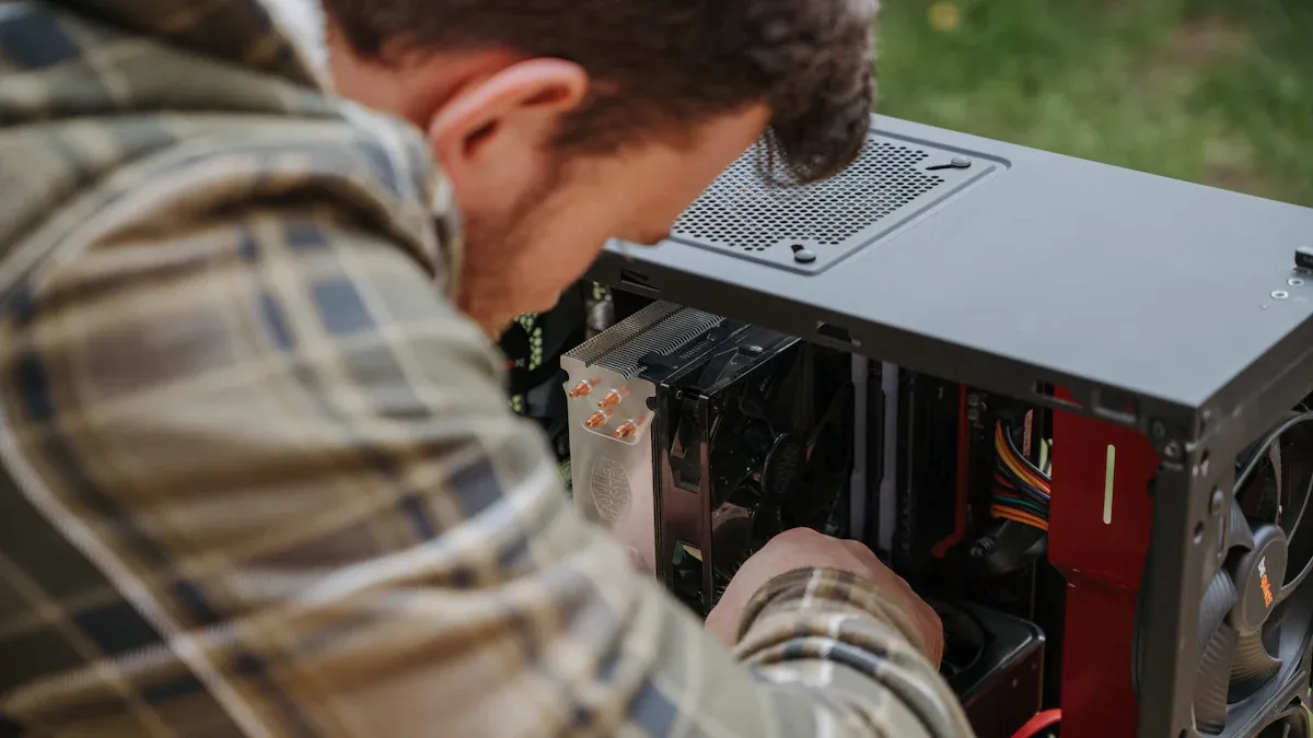
Preparing the Surface
Proper surface preparation ensures strong thermal contact and reliable performance. Technicians start by cleaning both the cold plate and the heat source with isopropyl alcohol or acetone. They remove all burrs and surface irregularities to create a smooth, flat interface.
Surface flatness should not exceed 0.001 inch per inch. For stubborn contaminants, methods like ultrasonic cleaning, abrasive blasting, or chemical cleaning may be used. Gloves or tweezers prevent recontamination after cleaning. After cleaning, the surface must dry completely before moving to the next step.
Applying Thermal Interface Material
A thermal interface material (TIM) fills microscopic gaps between the cold plate and the heat source. Technicians select TIMs such as phase change materials, hybrid gels, or gap filler pads for their high conductivity and reliability. They apply the TIM in a thin, even layer, usually between 0.002 and 0.004 inches thick.
Uniform application prevents air bubbles and reduces thermal resistance. Thicker or uneven layers can cause hotspots and reduce cooling efficiency. The right TIM choice and careful application improve heat transfer and device reliability.
Securing Cold Plates
After applying the TIM, technicians position the cold plate onto the prepared surface. They use mounting hardware and tighten screws to the specified torque, often between 8 and 20 in-lbs for M4 screws. A center-out torque sequence ensures even pressure and avoids warping. Proper fastening maintains stable contact and prevents leaks. Calibration tools help align the cold plate with system components for maximum effectiveness.
Connecting Fluid Lines
Technicians connect fluid lines to the cold plate using leak-tested fittings. They select compatible materials for tubing and couplings to avoid galvanic corrosion. Non-drip quick couplings prevent leaks during connection and disconnection.
Compact couplings save space in tight installations. Maintaining optimal flow with minimal pressure drop reduces pump stress and improves system efficiency. Long-term reliability of couplings ensures leak-free operation over time.
Common Mistakes
Misalignment
Misalignment often leads to uneven heat transfer and poor system performance. Technicians should always use alignment tools to ensure cold plates match the heat source location.
Poor Contact
Insufficient contact between the cold plate and the heat source increases thermal resistance. Gaps or air pockets form when surfaces are not flat or when the thermal interface material is applied unevenly.
- Always inspect for full surface contact before securing the plate.
- Use the correct amount of thermal interface material to avoid air gaps.
Improper Fluid Flow
Incorrect fluid flow direction or low flow rates can cause temperature spikes. Poorly placed inlets and outlets may create dead zones where coolant does not circulate.
Exposure to Elements
Environmental factors such as humidity, dust, and air temperature can degrade cold plate performance over time.
- High humidity and temperature increase frost buildup, which thickens the frost layer and reduces heat transfer.
- Dust and suspended particles settle on surfaces, promoting frost formation and fouling.
- Long-term exposure to dust and fouling leads to higher pressure drops and lower efficiency.
Regular cleaning and protective covers help reduce these risks.

Best Practices for Cold Plates
Maximizing Surface Contact
Maximizing surface contact improves heat transfer and system reliability. Technicians often embed coolant tubes directly into the metal plate. This method reduces thermal interfaces and boosts efficiency. Some designs use thermally conductive epoxy to fill gaps and prevent leaks.
Others press tubes flush with the plate surface, which removes the need for epoxy. Internal fins or pin fins inside the plate increase surface area and create turbulence. These features lower thermal resistance and enhance cooling. Custom cold plates may use microchannels or complex shapes to optimize coolant flow. Dual-sided plates can cool components on both sides, saving space and increasing performance.
Using Retention Brackets
Retention brackets secure cold plates and maintain even pressure. Proper brackets prevent movement and reduce the risk of leaks. Technicians should use brackets designed for the specific plate and system. Even pressure across the plate ensures stable contact and consistent cooling. Brackets also help align the plate with components, improving installation repeatability.
Uniform Component Placement
Uniform placement of components helps distribute heat evenly. Technicians should separate high-power parts across the board to avoid hotspots. Placing these parts centrally can promote balanced cooling. Arranging components in rows or columns supports both free and forced convection. Temperature-sensitive parts should stay away from heat sources. Adding thermal vias near hot spots improves heat conduction. Keeping a solid ground plane spreads heat and boosts dissipation.
Maintenance Tips
Regular maintenance extends the life and efficiency of cold plate systems. Teams should inspect cold plates, manifolds, and heat exchangers for leaks or blockages. Automated sensors can detect problems early and help optimize performance. Maintaining coolant levels and checking seals prevents failures. Ongoing training ensures staff can handle issues quickly. Redundant cooling systems reduce downtime during repairs. Routine evaluations keep the system running at peak efficiency.
- Establish a maintenance schedule for inspections and cleaning.
- Partner with vendors for timely support and upgrades.
Conclusion
Cold plate performance depends heavily on placement. By focusing on flat surfaces, proper alignment, and efficient fluid flow, engineers can improve reliability and reduce thermal issues. Strategic positioning is essential to meet the cooling demands of modern electronic and industrial systems.
For industry standards and best practices, refer to ASHRAE thermal guidelines.
| Parameter | ToneCooling Specification |
|---|---|
| Material | Copper T2 / 6061 aluminum |
| Welding | TLP diffusion welding |
| Test pressure | 1 MPa (He leak + N₂ hold) |
| Coolant | PG25 (25% propylene glycol) |
| Custom design | Yes — DXF/STEP accepted |
Frequently Asked Questions
Does ToneCooling offer OEM and ODM services?
Yes. ToneCooling provides full OEM and ODM services including custom design, prototyping, thermal simulation, and volume production. We serve customers in North America, Europe, and Asia-Pacific with engineering support and samples within 2–4 weeks.
What materials are used in ToneCooling liquid cold plates?
ToneCooling manufactures cold plates in aluminum (6061/6063), copper (C1100/C1020), and stainless steel. Aluminum FSW cold plates are ideal for high-volume EV and industrial applications, while copper brazed cold plates provide maximum thermal conductivity (398 W/m·K) for high heat flux electronics.
What is the typical lead time for custom cold plates?
Prototype samples are delivered within 2–4 weeks. Production orders typically ship within 4–6 weeks after sample approval. ToneCooling responds to all quote requests within 24 business hours.
Get a Custom Thermal Solution from ToneCooling
ToneCooling is a professional liquid cooling solution provider specializing in custom cold plates, AIO coolers, and advanced thermal management systems. With ISO 9001:2015 certified manufacturing, we deliver prototype samples within 2–4 weeks. Contact ToneCooling today for a free consultation and quote — we respond within 24 business hours.
Industry References & Standards
Need a Custom Liquid Cold Plate?
Cold Plates Positioning Placement is a high-performance thermal management solution engineered by ToneCooling for demanding applications.
ToneCooling engineers design thermal solutions for your specific requirements. Get an engineering RFQ review based on your uploaded requirements.
Semiconductor Test Fixture Cold Plate is a critical component in modern thermal management. ToneCooling engineers this solution for AI servers, data centers, EV batteries, and power electronics requiring high-performance liquid cooling.
Semiconductor Test Fixture Cold Plate: Key Specifications
When evaluating semiconductor test fixture cold plate, engineers consider thermal resistance, pressure drop, flow rate, and material compatibility. ToneCooling provides detailed specs for every semiconductor test fixture cold plate design, backed by CFD simulation and testing.
Why Choose ToneCooling for Semiconductor Test Fixture Cold Plate
ToneCooling has manufactured over 50,000 semiconductor test fixture cold plate units for global OEM customers. Our semiconductor test fixture cold plate production features vacuum brazing furnaces below 10⁻⁴ mbar, FSW machines with ≤0.02mm flatness, and helium leak detection at 10⁻⁸ mbar·L/s. Every semiconductor test fixture cold plate undergoes 100% pressure testing at 25 bar.
Our engineering team provides free semiconductor test fixture cold plate design consultation, CFD simulation, and rapid prototyping in 7-14 days. Production semiconductor test fixture cold plate orders ship in 4-6 weeks under ISO 9001:2015 quality management.
Need a Custom Liquid Cold Plate?
ToneCooling engineers design thermal solutions for your requirements. Response within 24-48 hours.
Last Updated: 2026-04-08
DR Kevin, Thermal Engineer, ToneCooling