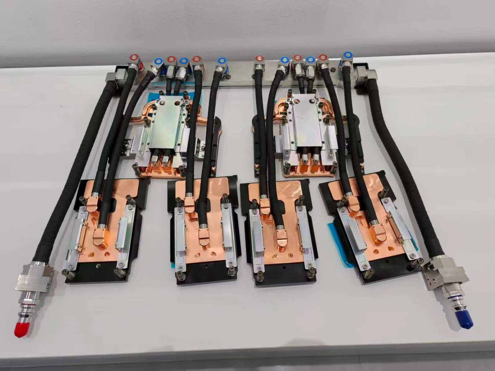
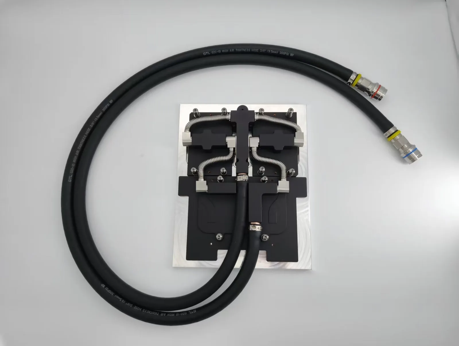
Vapor chamber wicks are usually sintered powder, mesh or grooves: sintered wicks work in any orientation and suit high heat flux, while mesh and grooves suit thinner or lower-cost designs. ToneCooling selects the wick for each custom vapor chamber.
Vapor chambers are among the most effective methods to dissipate heat in cutting-edge thermal management solutions for small, demanding applications such as smartphones, servers, gaming consoles, and LED modules.
The working fluid’s phase-change cycle, which induces the fluid to evaporate at the heat source and condense at cooler regions, provides them with the capacity to transport heat rapidly across a surface.
The structure of the wick is what enables capillary action, and it is the key component in this heat transfer. The wick returns the working fluid condensed back to the evaporator, keeping the cycle continuous without the use of gravity. The wick structure has a direct influence on the efficiency, response time, mechanical design, and difficulty of manufacture of the vapor chamber.
This article delves deeply into the most common wick structures utilized in vapor chambers, discussing their thermophysical properties, trade-offs in performance, and efficiency in undertaking specific engineering assignments.

Sintered Copper Powder Wick
To produce sintered wicks, copper powder is compacted and melted into a porous sponge-like configuration. The primary advantage of this kind of wick is that it has high capillary pressure, which allows it to consistently return liquid even under a great deal of heat and in various positions.
Key characteristics:
- Capillary strength: High due to tiny pores (10–50 μm) in the material.
- Transport of heat: Excellent when items are in a way that does not allow gravity to pull them downward.
- Low thermal resistance: It ensures that vapor and liquid get along well.
- Uses: Typical for use in laptops, CPUs, and telecom hardware.
However, sintered wicks are less permeable, which makes the flow of fluid slower and reduces performance if the heat flux is extremely high.
Copper Mesh (Screen) Wick
Copper mesh wicks consist of metal screens that are rolled up or stacked in the vapor chamber. They are permeable and can allow fluids to pass through them faster and with less resistance.
Key characteristics:
- Capillary force: Moderate.
- Permeability: High, with reduced drop in pressure.
- Thickness of chamber: Ideal for less than 1 mm-thick vapor chambers.
- Economical: It is simpler to manufacture and assemble.
Individuals tend to use copper mesh for ultra-thin consumer electronics such as tablets and smartphones. These products require extremely flat profiles without sacrificing thermal performance since they are extremely small.
Grooved Wick / Composite Wick
Grooved wicks are created by cutting linear or radial grooves in a base plate, regulating fluid flow. Grooves alone don’t allow much capillary action to occur, but when you combine them with mesh or sintered powders, they form composite wick structures that reconcile permeability and capillarity.
Key characteristics:
- Hybrid function: Balances the power of suction and the direction of flow.
- Heat spread: Grooves allow vapor to travel rapidly from side to side.
- Design flexibility: Allows you to create your patterns of flow to dissipate hotspots.
- Applications: Applied to devices with heat sources that are not uniform.
Recent studies indicate that groove-sintered composites (VC-G) have greater capability for spreading heat and initiating start-up than uniform wick structures.
Gradient / Biporous Wick
A gradient or biporous wick consists of pores of varying sizes throughout the wick region. The pores are typically small in the evaporator direction for enhanced capillary suction and larger in the direction of the condenser to reduce flow resistance.
Key advantages:
- Improved performance during startups: Rapid fluid movement during the initial rise in heat.
- Uniform temperature profile: A uniform temperature profile prevents hotspots from occurring.
- Optimal method of addressing heat flow: Avoids the drawbacks of high permeability and capillarity while achieving the merits.
In experiments, gradient-pore chambers achieved 63% thermal saturation in under 240 seconds, whereas wick-free designs took over 400 seconds.
Wick-Free / Patterned Surface Designs (Emerging)
Certain research studies explore wick-free vapor chambers, employing patterned or micro-structured surfaces in place of wicks to direct condensate via surface tension.
Key highlights:
- Simple design: Fewer manufacturing steps.
- Lightweight applications: Suitable for ultralight electronics and space.
- Cons: It is slow to start up and has slow capillary return.
These are still in the experimental stages and are being considered for certain applications where weight or thickness is highly critical.

Performance Comparison
Thermal Resistance and Heat Flux
Thermal resistance is a significant indication of the efficiency with which a vapor chamber operates. Comparative analyses indicate that VC-G (groove + sintered) wicks exhibit the lowest thermal resistance due to their hybrid nature. Wick-free chambers, however, exhibit significantly higher thermal impedance when the same power is applied.
Maximum Heat Transfer Rate
The pore size and wick shape greatly influence how rapidly heat travels through them:
- <40 µm: Copper mesh performs better since fluids are able to pass through it.
- 40–100 µm: Grooved and composite wicks perform best when the pore size is in the middle range.
- >100 µm: Sintered powder performs best since it has increased suction.
These observations assist in making wick selection choices by design engineers for the appropriate structures of wicks for the anticipated range of heat flow and application of the wick.
Temperature Uniformity and Start-Up Time
Gradient wicks are superior to uniform and wick-free configurations with regard to both start-up rate and temperature uniformity. Wick-free configurations require roughly twice the time to achieve operational thermal equilibrium, which may not be acceptable for electronics that require rapid turn-on.
Engineering Trade-Offs
Capillarity vs. Permeability
There exists a trade-off inherent:
- Sintered powder contains a great deal of capillary suction but little fluid flow.
- Mesh allows the fluids to move rapidly, but doesn’t have much suction.
- A composite is a compromise that is created to suit the operation of the system.
Wick selection will need to balance these characteristics for optimum return of the liquid and steady state, particularly in horizontally mounted devices or fast-cycling devices.
Thickness and Geometric Constraints
For products that require a chamber height of less than 1 mm:
- Mesh is preferred.
- Sintered wicks may not be effective since they are too large.
Composite and grooved options permit variable chamber profiles, but they complicate tools and materials.
Manufacturability and Cost
| Wick Structure | Manufacturing Complexity | Cost | Market Maturity |
|---|---|---|---|
| Sintered Powder | Medium | Moderate | Commercial |
| Copper Mesh | Low | Low | Commercial |
| Grooved / Composite | High | High | Industrial / Custom |
| Gradient / Biporous | Very High | High | Research-stage |
| Wick-Free / Patterned | Experimental | Not yet characterised | Emerging |
Wick Structure Selection Guidelines
In selecting wick structures, engineers should consider the following:
- High capillarity applications (such as vertical orientation): Utilize sintered powder.
- Very thin and low-profile systems: Select copper mesh.
- Heating irregularly and spreading rapidly: Select either grooved or composite wicks.
- For temperature-sensitive devices that have fast boot-up times, consider gradient or biporous wicks.
- For low-load, light environments, consider wick-free or micro-patterned surfaces.

Conclusion
The wick structure in vapor chambers is not merely a matter of design; it is the central component that determines how efficiently heat is transferred, distributed, and removed from sensitive electronics.
Engineers can make intelligent choices within system constraints and thermal performance requirements if they understand the advantages and disadvantages of each wick structure, including sintered, mesh, grooved, composite, gradient, or wick-free.
As thinner, more efficient cooling becomes increasingly necessary, innovative wick designs will remain a vital component of future thermal management.
For industry standards and best practices, refer to ASHRAE technical resources.
Frequently Asked Questions
Does ToneCooling offer OEM and ODM services?
Yes. ToneCooling provides full OEM and ODM services including custom design, prototyping, thermal simulation, and volume production. We serve customers in North America, Europe, and Asia-Pacific with engineering support and samples within 4–6 weeks.
How does a vapor chamber differ from a heat pipe?
A vapor chamber spreads heat in two dimensions across a flat surface, while a heat pipe transfers heat along a single axis. Vapor chambers are ideal for high heat flux applications like GPU cooling where uniform heat spreading is critical.
Get a Custom Thermal Solution from ToneCooling
ToneCooling is a professional liquid cooling solution provider specializing in custom cold plates, AIO coolers, and advanced thermal management systems. With ISO 9001 quality management and our own manufacturing facility in Huizhou, China, we deliver prototype samples typically within 4–6 weeks. Contact ToneCooling today for a free consultation and quote. An engineer reviews every RFQ and replies by email with next steps.
References: ASHRAE thermal standards
Why Choose ToneCooling for Vapor Chamber Wick Structure
Engineering review and prototype planning are based on the project requirements. Custom prototype lead time is normally 4–6 weeks after drawing approval and order confirmation; confirm the production schedule in the quotation.
Need a Custom Liquid Cold Plate?
ToneCooling engineers review your drawings and requirements and reply by email with next steps.
Last updated: 2026-10-02